X
 
  • Time
  • Show
Clear All
new posts
  • oilerlord
    Member
    • Mar 2015
    • 82

    #1

    Testing Panel Output (Used Panels)

    Hello everyone,

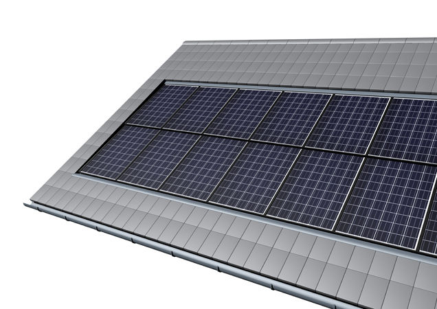
    My panels are going up on the roof at the end of July; a total of 41 SunPower SPR-225's. I bought them used, and have put a multimeter to them to make sure they all work (which they do). I aligned them more or less at the roof pitch angle, and tested them at an ambient temperature of 30C (86 degrees), in full sun, and after 30 minutes so they reached max temperature. Generally, a sample of 5 yielded the following results:

    42.95 Volts X 5.84 Amps = 250.82 Watts

    I did the same test a couple of months ago on a cool day in full sun which yielded over 260 Watts. The panels are rated at 225. My installer says that the high number that I'm getting is somewhat meaningless, and not to expect anywhere near those numbers. The ABB micro inverters I'm installing are rated at 96% efficiency, and the cable runs are quite short. In full sun, at a temperature of 20C, is it reasonable to assume that the panels have the ability to produce over 240 watts of usable power? Here are the factory specs:

    Electrical Data
    Measured at Standard Test Conditions (STC): irradiance of 1000W/m², AM 1.5, and cell temperature 25° C
    Peak Power (+5/3%) Pmax 225 W
    Efficiency η 18.1 %
    Rated Voltage Vmpp 41.0 V
    Rated Current Impp 5.49 A
    Open Current Voltage Voc 48.5 V
    Short Circuit Current Isc 5.97 A
    Maximum System Voltage UL 600 V
    Temperature Coefficients Power (P) -0.38% / K
    Voltage (Voc) -132.5mV / K
    Current (Isc) 3.5mA / K

    I was wondering if anyone else put a multimeter on their panels before their installation, and got similar results above factory specs and/or know the relation between testing on a meter vs actual performance. Thanks for sharing.
    oilerlord's 9.23kW Plant
  • inetdog
    Super Moderator
    • May 2012
    • 9909

    #2
    It is easy to measure Voc and Isc with a multimeter and IF you have a good idea what the orientation and the insolation are that can be used for comparison to manufacturer specs.

    But there are failure modes (weak cells, high resistance interconnects, blown bypass diodes, etc.) that will not show up at all in those simple tests.
    Ideally you would need to connect the panels one at a time either to a properly chosen resistive load or an MPPT device to find out approximately what the Vmp and Imp are.

    42.95 Volts X 5.84 Amps = 250.82 Watts
    Just how are you measuring those numbers? By connecting to and MPPT GTI or CC?
    The voltage looks like it could either be Vmp at STC or Voc for a very hot panel.
    The current is higher than Imp and close to Isc, which leads me to thing that you are actually measuring Isc. That is not useful in testing the panels. You could get Isc from a panel 2/3s of which is bad and the bypass diodes are allowing you to see the Isc of the remaining 1/3 of the panel.
    SunnyBoy 3000 US, 18 BP Solar 175B panels.

    Comment

    • oilerlord
      Member
      • Mar 2015
      • 82

      #3
      Originally posted by inetdog

      Just how are you measuring those numbers? By connecting to and MPPT GTI or CC?
      The measurements were done with a multimeter - contacting the +/- leads from the panels to the leads on meter. Yes, it's a hot day (where i live), 86F, and the panels were very hot after sitting in the sun for 30 minutes. Initially, (at ambient temperature) they read nearly 47 volts but as they heated up from the sun; they leveled out to just under 43. I only connected them for a couple of seconds each time because I didn't want to risk damaging them.

      It's also quite common for our temperatures to reach -20C (-4F) in winter, yet have clear sunny skies. For that reason, the ABB inverters were the only micro option that could handle the low temperatures / high voltage requirements for the permit.

      OK, so what you measured for current was Isc. You cannot use that current in calculating panel power. You need to decrease that proportionally to get Imp instead. That would be about 5.37A.

      And you measured Voc instead of Vmp, so at that temperature Vmp will be roughly your measured Voc times the nominal Vmp and divided by the nominal Voc.
      That is 42.95 times 41.0, divided by 48.5. Roughly 36V.

      36V times 5.4A gives you 196 watts, real world.
      Last edited by inetdog; 06-28-2015, 07:11 PM.
      oilerlord's 9.23kW Plant

      Comment

      • Sunking
        Solar Fanatic
        • Feb 2010
        • 23301

        #4
        Have you read this?
        MSEE, PE

        Comment

        • posplayr
          Solar Fanatic
          • Jun 2015
          • 207

          #5
          Originally posted by inetdog
          Ideally you would need to connect the panels one at a time either to a properly chosen resistive load or an MPPT device to find out approximately what the Vmp and Imp are.
          As an EE I understand internal impedance;, so my question is whether there panels follow a idealized Thevenin equivalent model (ideal voltage source in series with an internal impedance) around rated load.

          What is the standard means of testing a panel? Resistive load at rated output?

          To the OP, I don't think this is really thread jacking because the fundamental problem with your measurements is that they are all "unloaded". So the question becomes what is "a properly chosen resistive load"?

          Is it as simple as R_load = Vmpp/Impp=41.0/5.49=7.47 ohms.

          Rated Voltage Vmpp 41.0 V
          Rated Current Impp 5.49 A

          Standard sizes are 10 ohms so you can get four of these and bolt them in Parallel/Series and keep the same 10 ohms


          If you fiddle you can find something closer to 7.5 ohms but probably not really necessary unless you are trying to stress the panel beyond rated load.

          Comment

          • posplayr
            Solar Fanatic
            • Jun 2015
            • 207

            #6
            Originally posted by Sunking
            Have you read this?
            OK your link suggests short circuit load testing rather than rated load tests. What happens with a thin film panel? I assume they have less internal resistance and can not handle the short?

            Comment

            • Sunking
              Solar Fanatic
              • Feb 2010
              • 23301

              #7
              Originally posted by posplayr
              What is the standard means of testing a panel? Resistive load at rated output?
              Using a environmentally controlled lab using a xenon strobe light with an intensity of 1000 watts per square meter with controlled at 25 degree Celsius, and 20% humidity. You cannot test them. All you an do is test Voc and Isc.

              Panels are current sources and current varies with direct proportion of Solar irradiance input. You cannot use a fixed resistive load, it is a moving target. Only way you could use a fixed resistance is to control the Solar irradiance input of a calibrated source. That can only be done in a lab.
              MSEE, PE

              Comment

              • posplayr
                Solar Fanatic
                • Jun 2015
                • 207

                #8
                Originally posted by Sunking
                Using a environmentally controlled lab using a xenon strobe light with an intensity of 1000 watts per square meter with controlled at 25 degree Celsius, and 20% humidity. You cannot test them. All you an do is test Voc and Isc.

                Panels are current sources and current varies with direct proportion of Solar irradiance input. You cannot use a fixed resistive load, it is a moving target. Only way you could use a fixed resistance is to control the Solar irradiance input of a calibrated source. That can only be done in a lab.
                I should have clarified "standard", I meant for field testing or DIY. That would rule out any calibrated source of irradiance. So as the OP has rationally attempted to do, his test light source is to use the sun as an uncalibrated source. I think that is what we are talking about and what I meant. At zenith sunny day, what is he going to be able to quantitatively determine at the output. The results of any measurement whether Open Circuit, Short Circuit or a loaded test is going to be a function of the incident light ? Correct?

                You say the panel acts as if it is a current source, producing current in proportion to light. Does it act like an ideal current source for a given light input or does it have a Norton equivalent. By spec they sure seem to act like they have series resistance of a Thevenin equivalent. In fact are there not equivalent models and can they not be used to "test" output power at close to rated load with a resistive load?

                I have asked Inetdog what a "properly sized" resistive load is. He is the first to mention this. It also seems safer.


                EDIT: I guess I answered part of my own question.
                I looked at a spec sheet for a Astonergy panel and Impp (or rated ) and Ioc is essentially very close; so a short is as good as a 7.5ohm power resistor?

                Comment

                • inetdog
                  Super Moderator
                  • May 2012
                  • 9909

                  #9
                  Originally posted by posplayr
                  EDIT: I guess I answered part of my own question.
                  I looked at a spec sheet for a Astonergy panel and Impp (or rated ) and Ioc is essentially very close; so a short is as good as a 7.5ohm power resistor?

                  http://pdf.wholesalesolar.com/module...771.1434675899
                  A properly sized resistive load is one which will draw approximately Imp when driven by a voltage of Vmp.
                  If the light conditions are low, the current will go down and the voltage will drop below Vmp.
                  The problem with testing only Isc is that it gives you no idea how the panels will perform under load.
                  Take, for example, a panel whose cells by design have an Imp of 5A. Now take one cell in that panel and break it or otherwise damage it so that it can produce only 2A under the same conditions.
                  When you measure Voc it will still be correct.
                  When you measure Isc, the section of the panel which includes the bad cell will not be able to produce 5A and so the bypass diode will conduct, allowing the full Isc to be supplied.
                  Assume three bypass diodes and three subsections in the panel. Now if you load it with a proper resistive load or an MPPT input you will get a current of 5A (Imp) and a voltage of just ~2/3 of Vmp. That tells you the panel is damaged even though both Voc and Isc are normal.
                  SunnyBoy 3000 US, 18 BP Solar 175B panels.

                  Comment

                  • posplayr
                    Solar Fanatic
                    • Jun 2015
                    • 207

                    #10
                    Originally posted by inetdog
                    A properly sized resistive load is one which will draw approximately Imp when driven by a voltage of Vmp.
                    If the light conditions are low, the current will go down and the voltage will drop below Vmp.
                    The problem with testing only Isc is that it gives you no idea how the panels will perform under load.
                    Take, for example, a panel whose cells by design have an Imp of 5A. Now take one cell in that panel and break it or otherwise damage it so that it can produce only 2A under the same conditions.
                    When you measure Voc it will still be correct.
                    When you measure Isc, the section of the panel which includes the bad cell will not be able to produce 5A and so the bypass diode will conduct, allowing the full Isc to be supplied.
                    Assume three bypass diodes and three subsections in the panel. Now if you load it with a proper resistive load or an MPPT input you will get a current of 5A (Imp) and a voltage of just ~2/3 of Vmp. That tells you the panel is damaged even though both Voc and Isc are normal.
                    I can see that the Isc test is inconclusive given the internal structure of the panel (e.g. by-pass diodes). The panel has to achieve it's rated values to be operational but achieving that value is no guarantee that the panel is good. In other words it is confirmatory but not conclusive test.

                    So with the resistive load, you only have to measure voltage and power is V^2R? (assuming you have measured R). I guess R can change due to heating and to be precise you could use an amp meter and volt meter but with uncalibrated solar incidence does it really matter?

                    It has been my experience that you are less likely to get tricked when testing at full load. Seems to apply to solar panel functional tests as well.

                    Comment

                    • inetdog
                      Super Moderator
                      • May 2012
                      • 9909

                      #11
                      Originally posted by posplayr
                      I can see that the Isc test is inconclusive given the internal structure of the panel (e.g. by-pass diodes). The panel has to achieve it's rated values to be operational but achieving that value is no guarantee that the panel is good. In other words it is confirmatory but not conclusive test.

                      So with the resistive load, you only have to measure voltage and power is V^2R? (assuming you have measured R). I guess R can change due to heating and to be precise you could use an amp meter and volt meter but with uncalibrated solar incidence does it really matter?

                      It has been my experience that you are less likely to get tricked when testing at full load. Seems to apply to solar panel functional tests as well.
                      Yup. The problem is that the resistance needed to hit Vmp/Imp exactly is a function of the amount of light as well as the temperature and health of the panel.
                      If you can come within 50% of the ideal resistance, on the low resistance side, not the high resistance side, it should be good enough for a test. It will not catch marginal cells, but it will be more comprehensive than the simple Isc test. However the Isc test is so much easier that it is a good place to start.
                      SunnyBoy 3000 US, 18 BP Solar 175B panels.

                      Comment

                      • posplayr
                        Solar Fanatic
                        • Jun 2015
                        • 207

                        #12
                        Originally posted by inetdog
                        Yup. The problem is that the resistance needed to hit Vmp/Imp exactly is a function of the amount of light as well as the temperature and health of the panel.
                        If you can come within 50% of the ideal resistance, on the low resistance side, not the high resistance side, it should be good enough for a test. It will not catch marginal cells, but it will be more comprehensive than the simple Isc test. However the Isc test is so much easier that it is a good place to start.
                        But if you are testing several panels (individuals) of an array, then it would seem worth the extra little effort to just use a voltmeter attached to a dummy load to compare outputs as you go down the line. In my mind inconclusive tests are pretty much worthless especially if there are multiple potential faults that you only detect back at the full up level. You are back to square one.

                        Had you done the loaded tests and got similar output from each panel, what latent (panel) defects would you have not detected? The fact that all the voltages are the same is enough for you to know they (the voltages) are alright for whatever light and resistor you happen to have.

                        I'm not familiar with the MC4 plugs, but could you not just (make a test plug) and measure the panel voltage insitu without any dummy load and look for consistency of voltage?
                        Measure total and all the individuals should tell you plenty and be hard to get fooled.

                        Comment

                        • Sunking
                          Solar Fanatic
                          • Feb 2010
                          • 23301

                          #13
                          Originally posted by posplayr
                          I can see that the Isc test is inconclusive given the internal structure of the panel (e.g. by-pass diodes). The panel has to achieve it's rated values to be operational but achieving that value is no guarantee that the panel is good. In other words it is confirmatory but not conclusive test.
                          That is incorrect. The Voc test confirms the bypass diodes are working, and the Isc confirms th ecells are producing maximum rated current.

                          If you send a panel for replacement, or if the installer does it, the only check they make is Voc and Isc. If those check out the panel is good. Well assuming you test at noon on a bright sunny clear day.

                          A fixed resistor is not going to tell you much unless you just happen to be inputting 1000 watts/ meter2 which is not really possible. You can calculate what the fixed resistance from Vmp and Imp at 100% Solar Irradiance, but you would never see it happen in the field. Example a standard 100 watt 36 cell battery panel will have a Voc = 22 to 24 volts, Vmp = 18 volts, Imp = 5.55 amps and Isc = 6.25 amps. One would think the Resistance to test at is 3.24 Ohms. Connect that up and you woul dbe falsely led to believe the panel is bad because you will never get 18 volts out of it because 100% or 1000 watt/meter2 input is only a lab condition. Say the which is a real Irradiance is only 500 watts/meter square which is a real life value and that Resistance is up to 6.5 Ohm's at MPPT

                          A solar panel is a current source and all current sources are tested the same way. Open circuit voltage, and short circuit current. If it passes, the current source is good.
                          MSEE, PE

                          Comment

                          • inetdog
                            Super Moderator
                            • May 2012
                            • 9909

                            #14
                            Originally posted by Sunking
                            That is incorrect. The Voc test confirms the bypass diodes are working, and the Isc confirms th ecells are producing maximum rated current.
                            I really have to disagree with you on this one, Dereck.

                            The Voc test shows you that the bypass diodes are not shorted, and that all of the cells are contributing voltage. It cannot tell you that all cells are capable of delivering any current beyond what the meter draws.
                            The Isc test only shows you that at least one segment of the panel is working and that the bypass diodes on the other segments are capable of carrying current. The few volt total drop across the bypass diodes is not going to have a noticeable effect on the Isc of the remaining good segment of the panel.

                            The number of times that you have one or more weak cells may be small compared to panels which just do not meet their Isc at all, but it does happen and the combination of Voc and Isc testing will NOT find it. It is particularly likely to happen in panels that have suffered shipping damage but no visible cracks or panels that fell out of the QC limits on the production line. The production tests specifically test Vmp and Imp along with the other parameters.
                            On an MPPT input, you will see that with one weak cell the Imp is close to normal while the Vmp is much lower (depending on the number of bypass segments in the panel.)

                            We have had members troubleshoot their systems and find exactly this problem. You can also apply the same reasoning to strings of panels.
                            If Voc of the string and Isc of the string is good, you could still have one or more defective panels in the string, including panels that are almost totally open except for their bypass diodes.
                            SunnyBoy 3000 US, 18 BP Solar 175B panels.

                            Comment

                            • posplayr
                              Solar Fanatic
                              • Jun 2015
                              • 207

                              #15
                              Originally posted by Sunking
                              That is incorrect. The Voc test confirms the bypass diodes are working, and the Isc confirms th ecells are producing maximum rated current.

                              If you send a panel for replacement, or if the installer does it, the only check they make is Voc and Isc. If those check out the panel is good. Well assuming you test at noon on a bright sunny clear day.

                              A fixed resistor is not going to tell you much unless you just happen to be inputting 1000 watts/ meter2 which is not really possible. You can calculate what the fixed resistance from Vmp and Imp at 100% Solar Irradiance, but you would never see it happen in the field. Example a standard 100 watt 36 cell battery panel will have a Voc = 22 to 24 volts, Vmp = 18 volts, Imp = 5.55 amps and Isc = 6.25 amps. One would think the Resistance to test at is 3.24 Ohms. Connect that up and you woul dbe falsely led to believe the panel is bad because you will never get 18 volts out of it because 100% or 1000 watt/meter2 input is only a lab condition. Say the which is a real Irradiance is only 500 watts/meter square which is a real life value and that Resistance is up to 6.5 Ohm's at MPPT

                              A solar panel is a current source and all current sources are tested the same way. Open circuit voltage, and short circuit current. If it passes, the current source is good.
                              OK It seems we are discussing this characteristic which within the voltage limits of the cell is a current source proportional to solar power.


                              From the curve, it is pretty plain to see that the current is essentially independent of the outside load being only a function of solar irradiation (as you described a "current source"). Perhaps better described as a solar irradiation current source (i.e. the panel acts like a current source proportional to incident solar power).


                              If you need a test that is easiest to interpret then the Voc/Isc tests are pretty good as long as you understand that
                              a.) Voc can vary but is generally close to the rated output voltage and
                              b.) Isc is proportional to incident solar power.
                              In effect these two measurements are independent of the load although the Isc is still proportional solar power.

                              I can see why the Insitu measurements might be problematic as you have no reference and you are comparing one to the other and without a pair it just gets more confusing. And even the known load will have variability, but that variability is no worse than the solar current source. You can't look for rated Vmpp or Impp at less than rated solar power and expect to get the same answer. As mentioned above the Voc at least does not vary much.

                              I don't know much about solar panel failure modes, but here is one at least that a loaded tests would have detected whereas the Voc/Isc would have failed to detect. The load tests would need to be done with panel comparison to identify the culprit. Voc/Isc tests would not detect any series resistance correct?

                              Hundreds of thousands of Scheuten Solar Holding-manufactured solar modules have been declared a fire risk by the Dutch Food and Goods Authority (NVWA).

                              Comment

                              Working...