X
 
  • Time
  • Show
Clear All
new posts

  • bcroe
    replied
    Originally posted by HX_Guy
    That is correct. Took a little bit of logistics on my end to figure out the best way to do it since the "Blue" string has panels in 3 different locations but it worked out ok.

    I should probably do a large sticker label and stick it to the underside of the combiner panel cover showing the schematic of the wiring and then numbers the wires to correspond with the schematic so it's readily available if needed in the future.
    Yes, good to label everything possible. You'll be glad you did. My box inside has an insulating front
    panel which is convenient to label; these are sections of an online custom created bumper sticker.
    Also used a colored tape code on both ends of each wire. Bruce Roe
    Attached Files

    Leave a comment:


  • SunEagle
    replied
    Originally posted by HX_Guy
    That is correct. Took a little bit of logistics on my end to figure out the best way to do it since the "Blue" string has panels in 3 different locations but it worked out ok.

    I should probably do a large sticker label and stick it to the underside of the combiner panel cover showing the schematic of the wiring and then numbers the wires to correspond with the schematic so it's readily available if needed in the future.
    It might avoid confusion (at least to me) since you have multiple wiring paths with different size wires which for me makes it hard to understand the "circuit' for trouble shooting should it need it.

    Leave a comment:


  • HX_Guy
    replied
    That is correct. Took a little bit of logistics on my end to figure out the best way to do it since the "Blue" string has panels in 3 different locations but it worked out ok.

    I should probably do a large sticker label and stick it to the underside of the combiner panel cover showing the schematic of the wiring and then numbers the wires to correspond with the schematic so it's readily available if needed in the future.

    Leave a comment:


  • SunEagle
    replied
    Originally posted by HX_Guy
    SunEagle that goes back to what we were talking about before and this schematic...


    The thicker white wire is the corresponding DC- for the red DC+ wire coming from plug #2.
    Ok.

    So for my clarity the "Blue" string in your drawing consists of the wire going through your combiner box (using an MC4 connector) to panels on a different section of roof and then coming back on one of those Positive (red wire) MC4 plugs on the bottom of the box. And the Negative for the "Blue" string is coming into the combiner box from the 3/4" conduit running through your attic.

    Then the Positive wire for both the "Red" and "Yellow" string come into the combiner box though those Positive (red wire) MC4 plugs while the Negative wires for those strings come in through the Negative (white wire) MC4 plugs.

    Just for clarity you might want to label both the Pos and Neg wire for each "string" so (or someone else) knows which string to isolate if they need to work on it.

    Leave a comment:


  • HX_Guy
    replied
    SunEagle that goes back to what we were talking about before and this schematic...


    The thicker white wire is the corresponding DC- for the red DC+ wire coming from plug #2.

    Leave a comment:


  • SunEagle
    replied
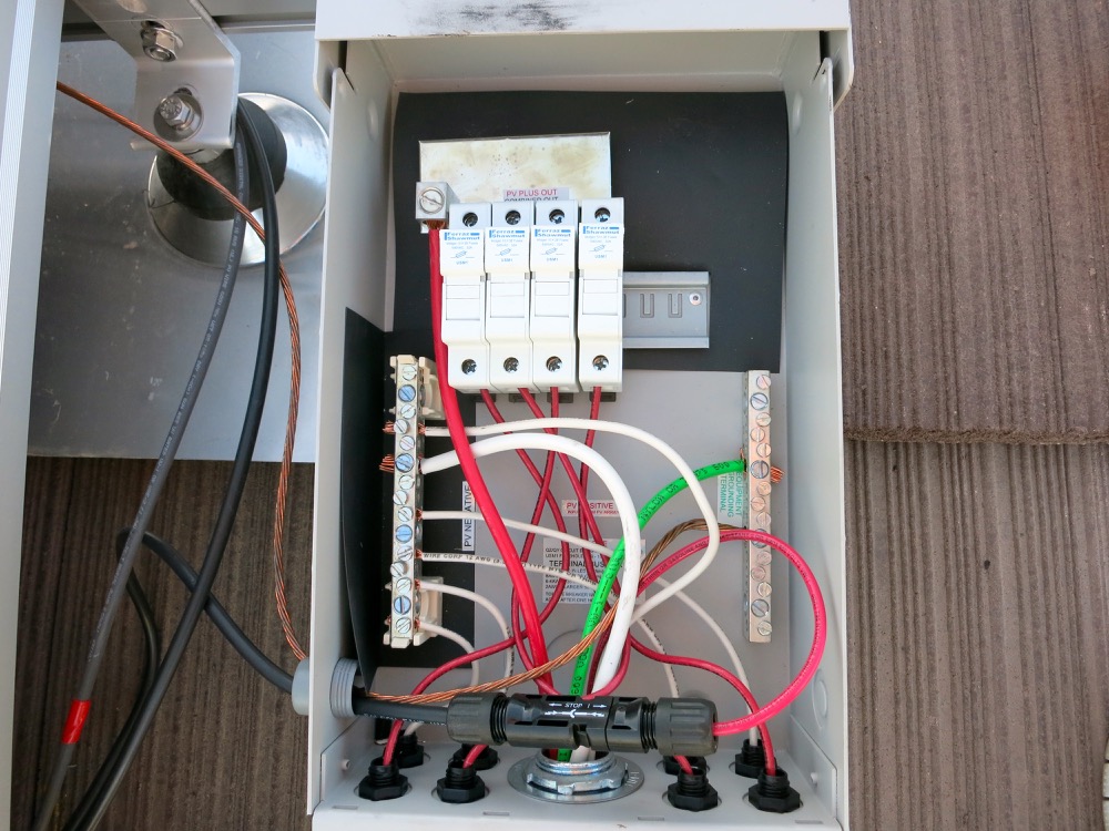
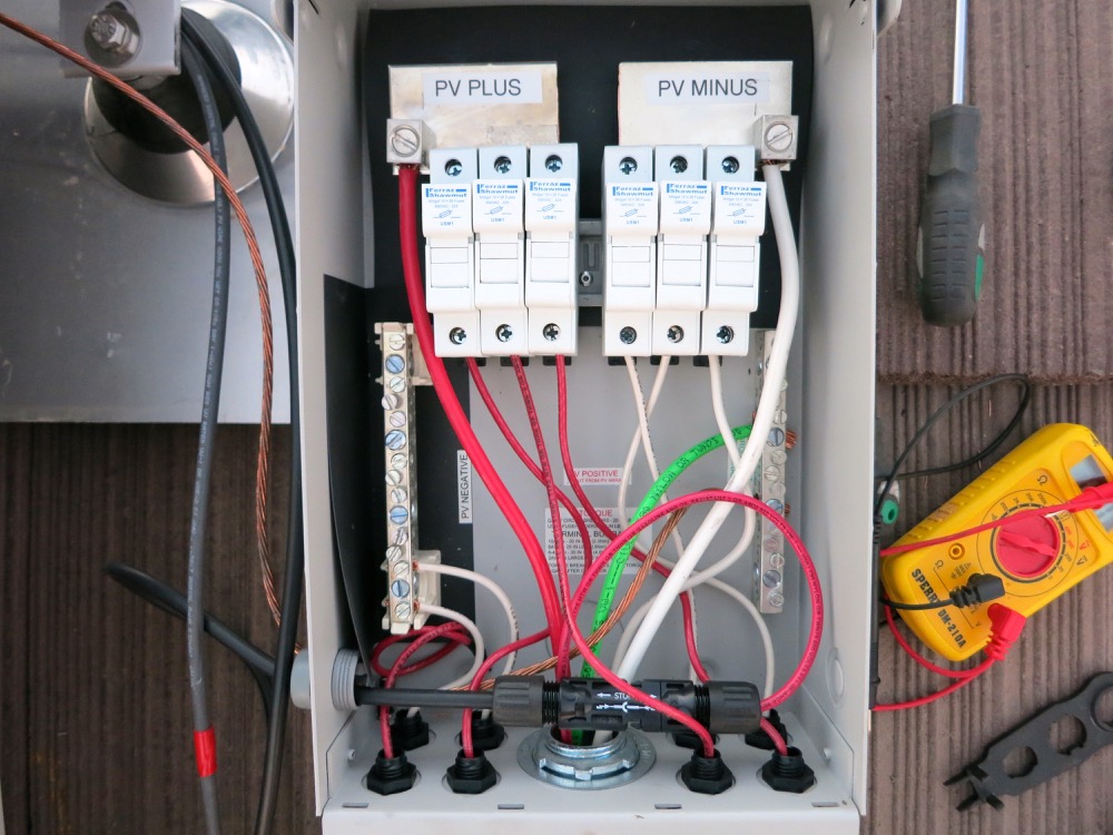
    The assembly looks good but I am not sure about the "White" wiring is correct.

    Based on the 3 red wires going to fuses, shouldn't the short white wire (the second from the left) that is now on that termination bar also go to a (negative) fuse?

    Also why is the larger white wire (coming out of the 3/4" conduit) going to a fuse? What is it for and does it need to be fused?

    Leave a comment:


  • bcroe
    replied
    Very nice, and labels are always more important than you first think. Someone didn't tighten
    the big lug on my combs, so I soldered them along with the bolt. Looks like you got the MC4
    disconnect tool. Mine kept breaking, so I made up well taped metal versions. Bruce Roe

    Leave a comment:


  • inetdog
    replied
    Very nice looking work. If I were the inspector I would not think that any modifications were done.

    Leave a comment:


  • HX_Guy
    replied
    Made the change to the combiner box, worked out nicely and looks quite professional.

    New parts...


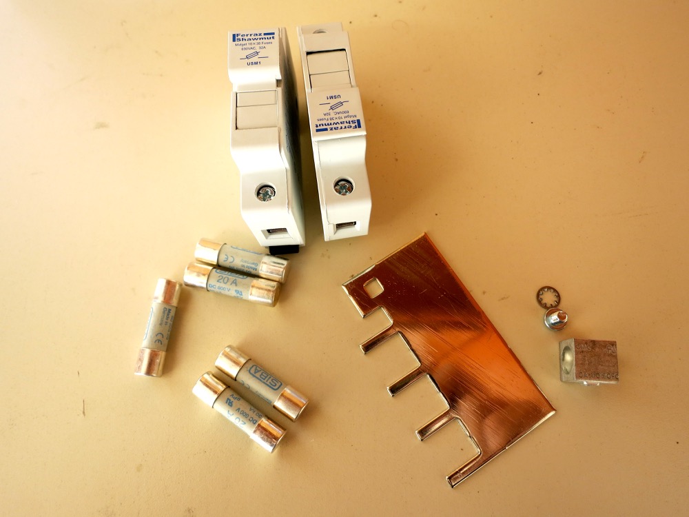
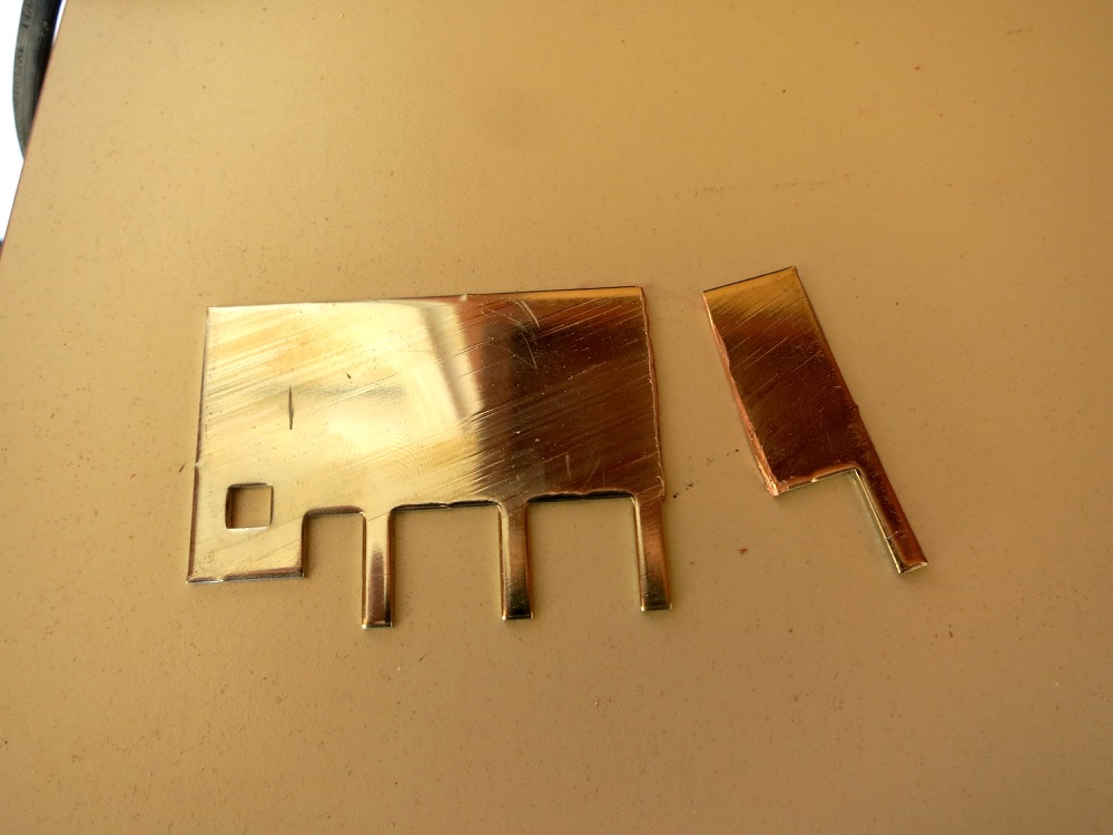
    Cut off the last leg as only 3 fuses are needed.


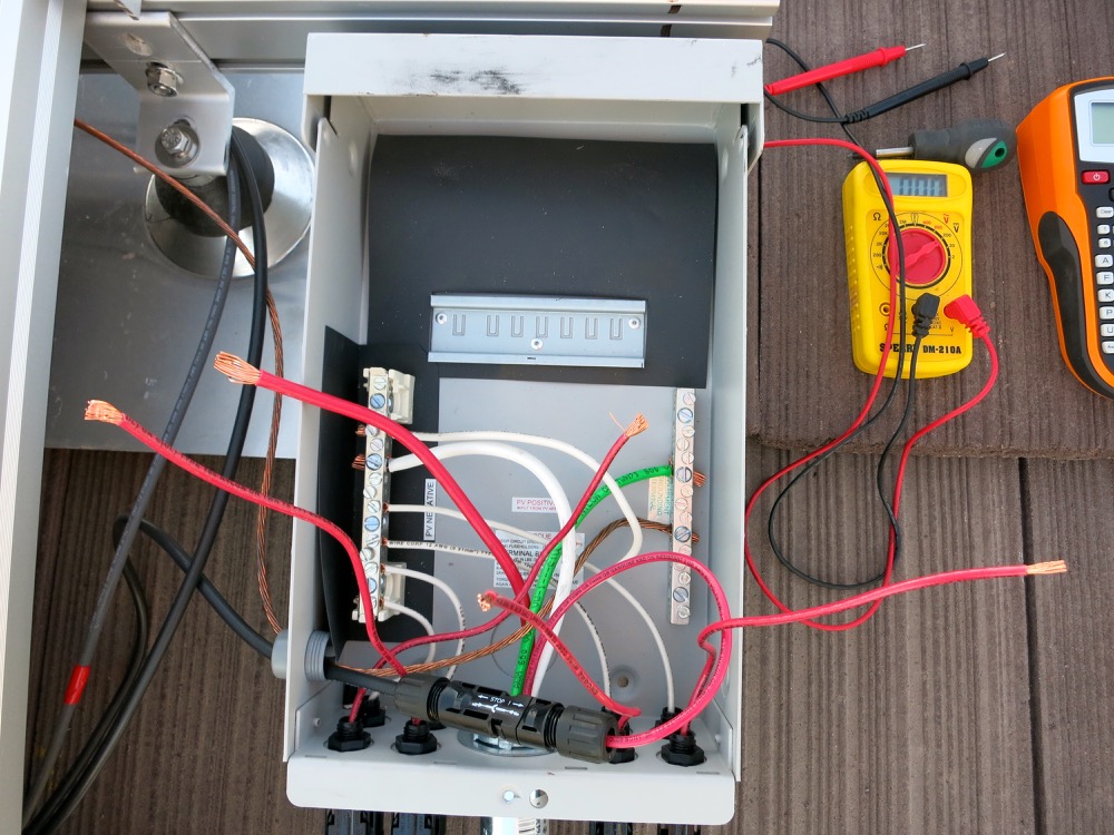
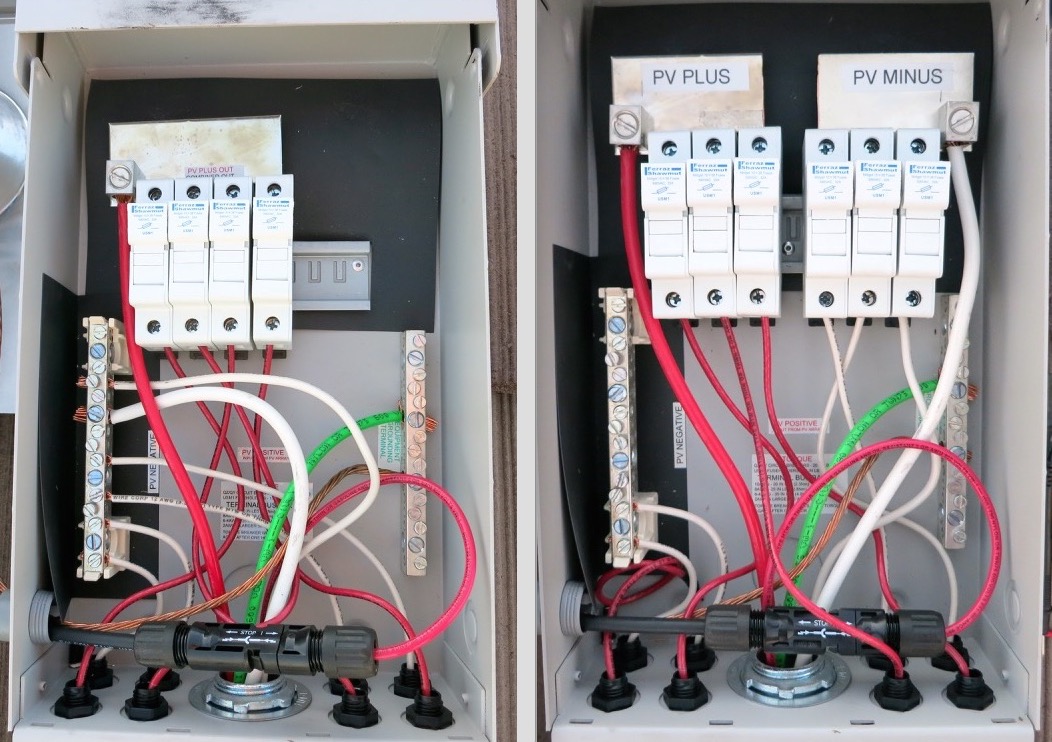
    Old combiner box setup with unfiused DC-


    Took out the old fuses off the DIN rail


    Put in new 20A fuses


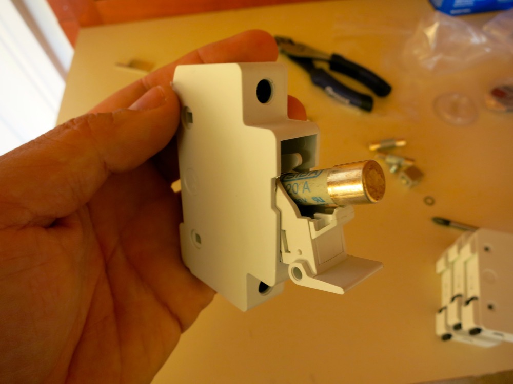
    Ready to re-install in combiner box


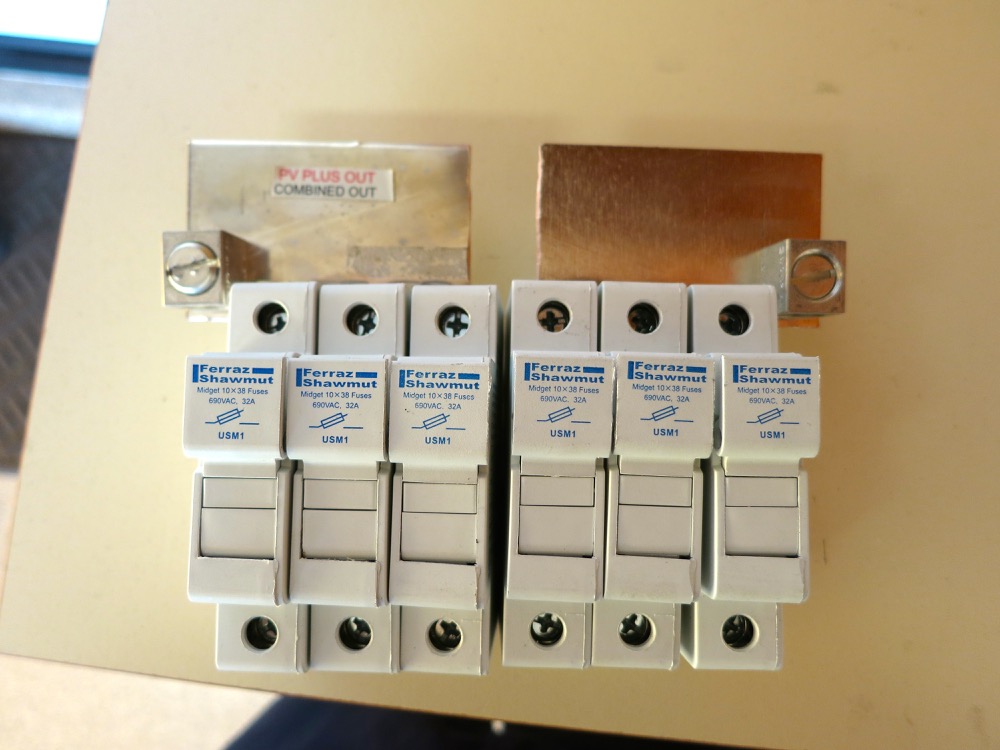
    And finished product


    Before and after

    Leave a comment:


  • foo1bar
    replied
    Originally posted by HX_Guy
    Thanks for checking Amy. Unfortunately the opening is only a 1/2" opening.
    Can you just use one of the connectors at the bottom?
    I think only 6 of the 8 are used, so you should have 1 male and 1 female that are spare.
    So why not have the wire for a spare connect to that red wire that's currently connected to the wire coming in the opening.

    Of course look at the gauges of the wires - I can't tell what they are - so maybe it wouldn't work because of that.

    But if that would work, then that 1/2" opening in the side is completely unneeded and can just be sealed.

    Leave a comment:


  • bcroe
    replied
    Originally posted by HX_Guy
    Thanks for checking Amy. Unfortunately the opening is only a 1/2" opening.
    A nice wrench driven metal punch will solve that problem; good to be able to make those
    holes whatever and wherever you need. Bruce Roe

    Leave a comment:


  • HX_Guy
    replied
    Originally posted by Amy@altE
    darn, I just tested it with a 3/4", just a wee bit to big to fit. If you can get a 1" one, you'd be golden.
    Thanks for checking Amy. Unfortunately the opening is only a 1/2" opening.

    Leave a comment:


  • Amy@altE
    replied
    Originally posted by HX_Guy
    Yes but I would still need to fit the connector though the round part that tightens it all together, no?
    darn, I just tested it with a 3/4", just a wee bit to big to fit. If you can get a 1" one, you'd be golden. (I'm not sure what size that hole is in the box)

    Leave a comment:


  • HX_Guy
    replied
    Originally posted by SunEagle
    Looks like you have a good action plan that will work.
    Yep, just put an order in for a new finger busbar, 2 fuse holders, and 6 20A fuses.

    Leave a comment:


  • SunEagle
    replied
    Originally posted by HX_Guy
    Also I had a chance to get up on the roof and inspect the combiner box situation a little closer and it seems the install will be a little easier and cleaner looking than I originally imagined.

    The 6AWG white wire (going to the inverter) does indeed reach up to where I could put in another busbar similar to the PV+ busbar at the top. Plus, the leads for the PV- coming from the MC4 connectors reach all the way up to the fuse holders as well, I thought I was going to need to replace those with new MC4 connectors with longer wires. Also, 2 more fuse holders definitely fit on the DIN rail.
    Looks like you have a good action plan that will work.

    Leave a comment:

Working...