-
-
How many strings do you have? (I'm guessing 3?)The Solaredge inverter will accept 2 strings, so you could just combine 2 of them on the roof and run one down separately... That would take another revision, but get you away from 2awg.
BenComment
-
Alright guys I have some fresh new content here this morning from SolarEdge.
SolarEdge send me a few PDFs on how their system is supposed to be calculated and items that I should be able to send to the city if I redo the permit.
Calculating Vmp, Imp, Voc and Isc
Voc and Isc Explained
Concept of Operation
So, it seems what the City really cares about here is Isc, the other ones really don't matter as far as I can tell in figuring out what conductor size to use.
Looking at this though, it seems ever more confusing however than before because in the Voc/Isc Explained document able, it specifically says:
"For cabling calculations related to maximum current (i.e. wire gauges), use the maximum output current as appear in the power optimizer data sheet"
Additionally, in the Calculation PDF, it says:
"The maximum current value of 15 amps should be used to determine DC output circuit conductor size and overcorrect protection requirements. The value of this labeling requirement should be 15 amps per string of power optimizers. Since SolarEdge inverters can be fully loaded with either 1 or 2 strings, the value would be either 15 or 30 amps."
How is that in any way clear for the City?
So even SolarEdge says to use the maximum output of the optimizers for sizing wires, regardless of what the inverter input is.
Well the maximum output of the inverters is 15A per string. With the original 4 strings, that would be 60A that need to be accounted for, and since it's DC, the city wants to see x1.25 and 1.25 again...so you've got 60A x 1.25 x 1.25 = 93.75A, and that's before any temperature correction!! Am I understanding that right?
Now for my system of 3 strings, it would be 45A x 1.25 x 12.5 = 70.31A which is still astronomical. Seems the only way to satisfy a normal size conductor would be with 2 strings, or 30A total which would give you 46.88A before temp corrections.Comment
-
You've almost got it. It looks like these documents are a newer revision than the code compliance document I listed earlier, and eliminate the alternatives for calculating the DC output current. 15 A makes sense to use as the rated output.
You only need the 1.25 * 1.25 correction when looking at PV Source and PV Output circuits [690.8(A) and 690.8(B)(1)(a)]. Look at the document SolarEdge just provided you. The PV Source circuit is between the panels and the optimizers. The output of the optimizers is a DC output circuit, and only needs a single 1.25 correction, even when there are multiple strings combined. Because this wasn't clear in 2011 NEC, some additional definitions were added in 2014 NEC that help. However, the interpretation should not have changed.CS6P-260P/SE3000 - http://tiny.cc/ed5ozxComment
-
Yeah, but my city is using 2011 NEC and apparently, at least according to the designer, is using the 1.25 twice for DC. I guess they could be educated on the matter but still the numbers are pretty high.
If you have 4 strings, that would need to be calculated as 60A x 1.25 = 75A. A #2 wire on the roof would be rated for up to 84.5A after temp correction (based on 130A @ 90º C). Makes sense why the permit says 2AWG then I guess.
If I were to redo my permits, a #6 would still work apparently though, but I would have to show the new string configurations and everything, and hope they understand to use 1.25 only once, not twice. I don't have a lot of faith in that happening. Though with the conduit now in the attic, the derate is much lower (is it the standard .82 or something else?) and it may still work even with doing 1.25 twice.Comment
-
But if you combined 2 of the 3 strings on the roof in the combiner and then ran the last string down separately, that would do it.Comment
-
As a newbie here, I didn't understand the distinction and implications for wire ratings between the setup I am considering (panels directly to a charge controller) and yours (optimizers). sensij appears to have gone to the crux of the matter of the difference between PV Source and DC output. I was very annoyed at having to multiply by 1.25 * 1.25 in sizing my PV Source wires - but for my situation it is required. My gut reaction to your concern, assuming sensij is correct and it sounds like they are, would be there should be a way of educating the city on this point. I'll keep watching the conversation out of interest...Comment
-
Listen, I understand your design company is being professional about this and really trying to help, but based on what they've put in the permit so far, I'm not sure you can rely on them to be an accurate source of information. If you re-do the permit, make sure that each circuit is called out by name: PV Source, DC Output, Inverter Input, Inverter Output. Show the calculation specific to each circuit, don't just lump DC and AC calculations and corrections together. When referring to equipment on the line diagrams and in the data sheet attachments, make sure the optimizers are called "DC Utilization Equipment". That should help make it clearer for the city, even in the 2011 version of code.CS6P-260P/SE3000 - http://tiny.cc/ed5ozxComment
-
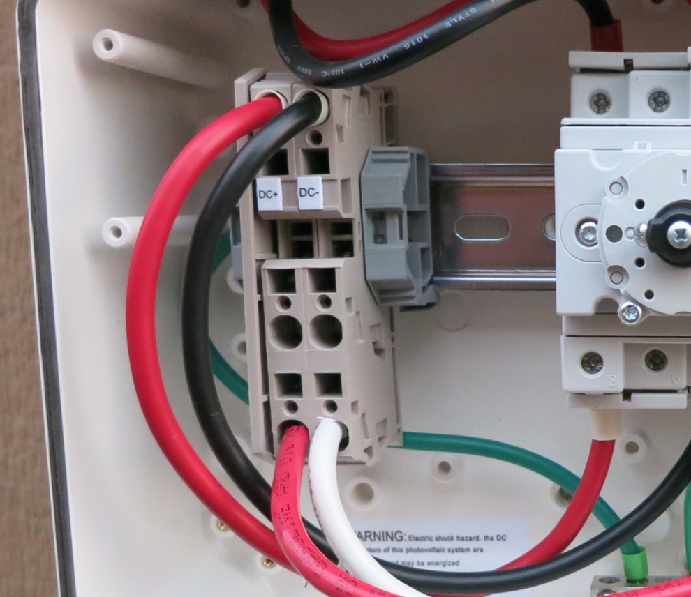
The SolarEdge inverter has terminals for only one string. The inverter's built-in overcurrent protection is sized for two strings, which is why they say they can handle two. If you run two strings, you would still need to parallel them in a combiner ahead of the inverter. Also, by running two strings to the inverter, now you've got 4 current carrying conductors in that FMC, and would need to apply yet another correction factor that has so far been avoided.CS6P-260P/SE3000 - http://tiny.cc/ed5ozxComment
-
Whoa, here's one out of left field!
I've been emailing back and forth with SolarEdge about this issue and trying to get some sort of documentation to show the City that the inverter will never have more than 34.5A running through the conductors but that their paperwork is unclear on this. I get this email back just a bit ago...
"The City is correct in taking the number of strings x 15 amps x 1.25 for sizing the conductors between a 3 string combiner and the inverter since this would be the available current in a fault condition. The inverter maximum input current vs calculated current would be used for calculating nominal operating current for the system labels."
I did not see that coming! So it seems nothing is wrong with the permit after all? Based on 4 strings, thats 60A x 1.25 = 75A. With rooftop conduit (as originally shown) a derate of 65% would mean the wire needs to be rated at least 115A @ 90º C. The smallest wire that meets that is in fact 2AWG.Comment
-
Definitely spots for 2 strings on all Solaredge dc disconnects. I don't combine on the roof unless absolutely necessary. Not sure on the conduit fill and temp corrections off hand though.Comment

 Tweet
Tweet


Comment