OK everyone, I deleted all my posts that argued about the return wiring and not taking into account the voltage drop on the return as well. You guys are right. Didn't need to read sensij's link though. Just needed to come to my senses.
Guess I had too many beers tonight and argued out of my *ss, LOL!
For those who still have unanswered questions about the SolarEdge system architecture, they have a white paper available on their website that explains in detail how their systems should be understood in the context of code. A copy of it is here: SolarEdge System Design and the NEC.pdf.
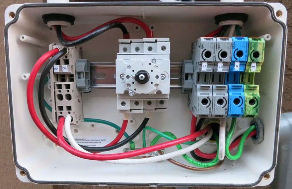
Not that you need anything else to worry about, but as I was re-reading the SolarEdge document I just posted, there was some text about the combiner box that reminded me to go back and look at your picture in this post.
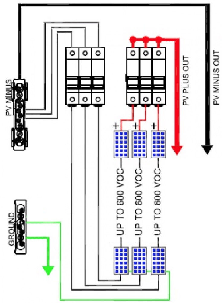
Your combiner box appears to have two problems:
1) White wire was used for the DC- conductors. In a SolarEdge system, these conductors are floating, not ground referenced. Only ground referenced conductors may be white.
2) The fuses are only on the DC+ wires. Since it is not ground referenced, fuses are required on the DC- wires as well. Those fuses were shown on your permit drawing, so there is a good chance this will fail inspection if the inspector sees it.
Using this combiner is a safety problem and it should be replaced with the permit approved model or an equivalent even if the inspector misses it. The text from the SolarEdge document specifically calls this out:
Note: In rare cases where three or more strings of power optimizers are wired in parallel, fusing will be required to protect the wiring between the power optimizers and the inverter. Because the circuit conductors are not grounded, fuses would be required in both the negative and positive conductors. The recommend fuse size of 20 Amps is calculated using the 15 Amp continuous output current limit of the power optimizer multiplied by 1.25 in accordance with NEC Articles 210.19 and 240.4.
Your FMC routing might run afoul of the codes cited in this paragraph:
Conductor Routing Single conductor cables in exposed outdoor locations within the PV array are permitted by NEC Article 690.31 (B). Article 690 Section IV, requires all DC conductors to be contained in a metallic raceway once they penetrate a building. In addition, beginning with the 2011 code, these raceways must be run along structural members, must be labeled with “Photovoltaic Power Source” every 10 feet, and on every section that is separated by enclosures, walls, partitions, ceilings or floors. The DC raceway must be at least 10 inches below the roof sheathing where it is not immediately below the PV array. Note that a type MC metal clad cable also meets the raceway requirement.
With regard to the questions about ground conductor size, the relevant sections of code are cited. For a 60 A breaker in this case, a minimum of 10 AWG is required. Note that any place the EGC is is not protected (IE, not in conduit), 6 AWG is the minimum.
The equipment grounding conductors should be sized and installed in accordance with the requirements of Articles 690.45(A), 690.46 and 250.122.
I had included a bad link earlier in the thread. The thread discussing the size of the AC conductors is this one.
All code cited is NEC 2011. There are definitely differences in versions earlier and more recent, but this is what I understand to be in effect in the OP's location.
My permit actually shows #10 ground between the inverter and through the disconnect to the main service panel, though the installer put in #8.
For the hot and natural, he put in #6, though the permit says #4.
There is also a #6 bare ground wire running from the inverter to the existing grounding electrode (but it doesn't pass through any conduit or other meter/disconnect boxes).
My rating is 47.5A for a 12.4kW system going to a 60A breaker.
To what did he connect that bare 6 AWG ground wire inside the inverter? A wire from the inverter straight to the electrode would be required in a transformer based inverter, to ground reference the DC side. If he ground referenced the DC side on this, that should fault the inverter, so hopefully it is just connected to the same ground terminal as the 8 AWG. I don't know how that terminal would accept two wires though.
Also, the way you screwed in the ground in the AC disconnect is not really right. It should be a listed lug, like that shown in this picture. You don't even need any extra wire to do it right, it looks like the looped green wire is long enough to get out to a lug and back with changing anything else.
You can actually have up to 25 panels per string, but no more than 5250W DC,
which is why my string is 16 panels.
The way I understand it, if you have shading issues or different orientations, the more panels per string, the better.
Here is a long video on the SolarEdge Optimizers, but the explanation on how they work starts at 21:25.
Thanks for that info. It sounds like my idea was on the right track. IN ADDITION, their inverter
communicates with the power boxes to set the output voltage of each one. That is how they
maintain a 350V string voltage. I didn't hear an explanation of how that communication is done.
This system does solve problems with shading and odd numbers of panels. The claim of 15%
more energy might apply in a difficult situation like that. I don't think they would have any
advantage over a straight forward ground mount string system that had no complex mounting
restrictions. About the only advantage I see over micro inverters, is running a higher DC
voltage over the distance to the inverter/AC connection point. The complexity of the communication
system would worry me, will my HAM transmitter throw it off? And troubleshooting could really
be a problem if something started failing; instead of a few simple parts, you have a community
of computers.
As for your DC wiring currents, they will be the array power output divided by 350 VDC. If that
is conservative, hopefully it will handle any fault situation safely. They keep talking about not
needing fuses with a minimum of long strings. But those long strings will then have a large
current capability outputted from the optimizers, needing larger wire and for me, fuses. I'm
glad to keep it very simple on the ground. Bruce Roe
Thanks for that info. It sounds like my idea was on the right track. IN ADDITION, their inverter
communicates with the power boxes to set the output voltage of each one. That is how they
maintain a 350V string voltage. I didn't hear an explanation of how that communication is done.
The communication is DC powerline... in other words, embedding a low power AC signal in the 350 DC voltage. I checked their patent and have been otherwise unsuccessful at finding information about what frequency the signal is at. I might try to put a scope on mine when it is running to see if I can find it. I doubt it would interfere with radio transmissions, and it is relatively reliable method of communciation.
Originally posted by bcroe
This system does solve problems with shading and odd numbers of panels. The claim of 15%
more energy might apply in a difficult situation like that. I don't think they would have any
advantage over a straight forward ground mount string system that had no complex mounting
restrictions.
Advantages over an unshaded and single orientation array is probably not much. Maybe a percent or two eventually as modules degrade and/or foul differently and some mismatch works its way into the system.
Originally posted by bcroe
About the only advantage I see over micro inverters, is running a higher DC
voltage over the distance to the inverter/AC connection point.
By keeping the inverter circuitry out from under the panels, where it is presumably hotter, SolarEdge makes a case for better reliability than micro-inverters. In terms of performance though, yes, there isn't much. The are close enough that both manufacturers have been able to create test arrays that "prove" their product is better. Some of SolarEdge's marketing material on this is here. I'm sure an Enphase fan could produce something similar.
Your combiner box appears to have two problems:
1) White wire was used for the DC- conductors. In a SolarEdge system, these conductors are floating, not ground referenced. Only ground referenced conductors may be white.
2) The fuses are only on the DC+ wires. Since it is not ground referenced, fuses are required on the DC- wires as well. Those fuses were shown on your permit drawing, so there is a good chance this will fail inspection if the inspector sees it.
Using this combiner is a safety problem and it should be replaced with the permit approved model or an equivalent even if the inspector misses it. The text from the SolarEdge document specifically calls this out:
It won't fail inspection because the inspector does not go on the roof here, so he won't even see it.
I would like it done right though, and I should have bought the specified Sunny Boxy SBCBTL6-10 combiner instead of the one I did, I only got the one I did because it was 1/2 the size and was pre-wired (I liked the MC4 connectors on there, thought it would be a cleaner install)..pricewise they are about the same. It shouldn't be too much of a problem to swap them out I don't think.
Also to confirm, it says I need 20A fuses, is that correct? My combiner uses 15A fuses right now and the permit spec'd 15A as well.
EDIT: Or another thought...can fuses be added for the DC- inside the combiner box I already have in place? I would only need 2 more fuse holders (only using 3 out of 4 now) and then run the DC- wires to the fuse holder input and a wire from each out to the DC- terminal block that's there now.
This is what I'm imagining, would this be possible? Any negative side to doing this?
Originally posted by sensij
Your FMC routing might run afoul of the codes cited in this paragraph:
I believe I followed all the rules stated in that paragraph so there shouldn't be a problem there.
To what did he connect that bare 6 AWG ground wire inside the inverter? A wire from the inverter straight to the electrode would be required in a transformer based inverter, to ground reference the DC side. If he ground referenced the DC side on this, that should fault the inverter, so hopefully it is just connected to the same ground terminal as the 8 AWG. I don't know how that terminal would accept two wires though.
He connected it to the grounding terminal inside the inverter's disconnect box, is this method ok?
Originally posted by sensij
Also, the way you screwed in the ground in the AC disconnect is not really right. It should be a listed lug, like that shown in this picture. You don't even need any extra wire to do it right, it looks like the looped green wire is long enough to get out to a lug and back with changing anything else.
I asked the guy at Home Depot for a grounding lug, he gave me a baggie of green grounding screws and said that's what I need.
Would a copper one be good, like this one on Amazon?
He connected it to the grounding terminal inside the inverter's disconnect box, is this method ok?
I asked the guy at Home Depot for a grounding lug, he gave me a baggie of green grounding screws and said that's what I need.
Would a copper one be good, like this one on Amazon?
Something else I noticed on an earlier picture concerning the Meter Box. The original installer ran that conduit from the left side which was removed. You will need some type of plug to make it weather tight.
Last edited by SunEagle; 01-11-2015, 11:54 AM.
Reason: i id the wrong box with the hole in it.
He connected it to the grounding terminal inside the inverter's disconnect box, is this method ok?
I asked the guy at Home Depot for a grounding lug, he gave me a baggie of green grounding screws and said that's what I need.
Would a copper one be good, like this one on Amazon?
I don't know if someone else already commented on this - I would scrape a bit more paint off than is shown in the picture a few pages back - so the lug surface area in completely in contact with bare metal. Looks like this job is finally coming to reality - quite a saga. Congrats.
The communication is DC powerline... in other words, embedding a low power AC signal in the 350 DC voltage. I checked their patent and have been otherwise unsuccessful at finding information about what frequency the signal is at. I might try to put a scope on mine when it is running to see if I can find it. I doubt it would interfere with radio transmissions, and it is relatively reliable method of communication.
Its probably akin to the X10 stuff that's been around so long. Have some info on it
somewhere, but never actually measured anything. I don't expect it to interfere,
was more worried about it being interfered with. Bruce
Something else I noticed on an earlier picture concerning the Meter Box. The original installer ran that conduit from the left side which was removed. You will need some type of plug to make it weather tight.
He connected it to the grounding terminal inside the inverter's disconnect box, is this method ok?
The grounding in the safety switch looks ok to me. The DC wiring, on the other hand, looks off. Firstly, a white DC- wire shouldn't pass inspection. 2nd, what's with the color change of red to black and black to red going through the switch? You aren't in the same terminals shown in the manual, although maybe there is continuity that makes it ok. I know you've been producing power so it must be right, but it doesn't look it to me.
For reference, here is the picture from the manual:
Modifying the combiner box as you suggested is probably not OK. One of the things about code is that all components used must be UL listed for that purpose. Making changes to the combiner box, even if you do everything right and use a listed fuse block, might still not be compliant. Like many things electrical... it will work, but it isn't right. It would be better to do that than leave it as-is, though.
The problem with your AC disconnect ground isn't so much the ground screw, but the way you put more than one conductor in the conduit bushing. If that lug was only listed for one conductor, putting two in it isn't compliant. A clean solution would be to get rid of that extra solid conductor pigtail, and instead cut and strip the green ground wire in the loop so that you have two ends. Those ends could both be grounded to the enclosure using something like this.

 Tweet
Tweet


Comment