-
I was pretty sure the step down transformers could also be used to step up the voltage but I am wanting to get split phase US standard 240v from 120v generator and I think many of the transformers I saw were European standard step down that would probably give european style single phase output and thus I don't think they would give split phase 240v in reverse. Any suggestions appreciated. -
I've also observed many imported variac style transformers, that can be used as step-up transformers too.
variable transformer 3KVA 240VACLeave a comment:
-
I also would like to use a small quiet inverter generator like the honda 2000 to charge the solar batteries or generally boost system output. I am considering a system with a Sol-Ark 12 and it only accepts 240 volt generator. What is the easiest and hopefully economic autotransformer to use or modify to covert the 120v to 240v split phase ? When I look on eBay most are step down transformers , can these be wired with secondary as primary if windings not connected?Leave a comment:
-
1) Chris Olson no longer on this site. sad
2) You want a transformer with a KVA rating of as large or larger than your generator. So a 9KVA rated transformer would work. Smaller would work, but when it saturates at it's full load, power throughput falls off, and heat builds rapidly
> AC Maximum Output Starting Watts 8125
Leave a comment:
-
Feel free to move this to a new thread if that would make more sense.
For those of us looking to implement a new transformer (auto or otherwise) to phase balance 120V and 240V loads across a 240V split phase genny output (Generac XP6500E) is there a preferred product?
AC Rated Output Running Watts 6500
AC Maximum Output Starting Watts 8125
Rated AC Voltage 120/240 VAC
Rated AC Frequency 60 Hz
Rated 120/240 VAC Amperage 54.2/27.0
Max 120/240 VAC Amperage 67.7/33.9
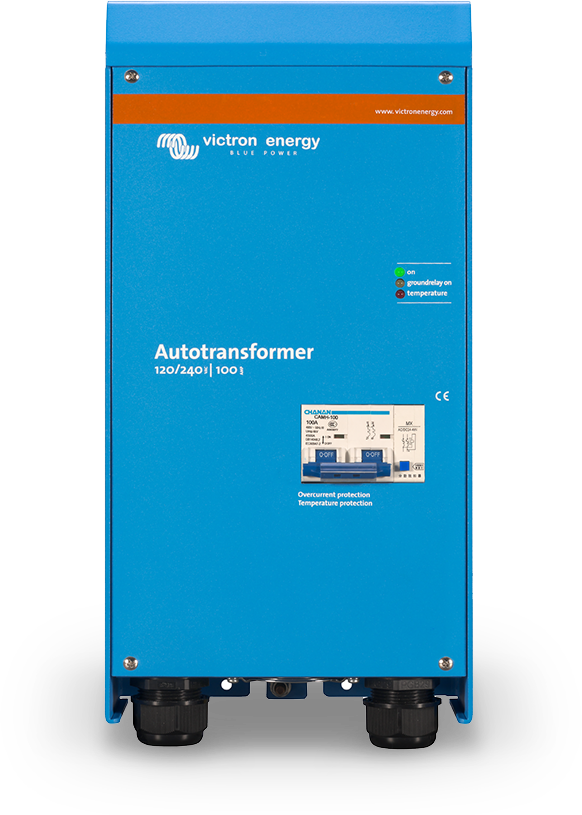
Many folks seem to like the Outback PSX-240 (Autoformer with Housing and fan)

But I was thinking that this Victron might be as good or better
Any thoughts? ChrisOlson, I know you and your neighbor have the Outback.
I'm not looking to build something custom. But wiring up cords, etc. as needed is not a problem.
Currently using extension cords when the power goes out. Hoping to step up to a manual transfer switch at some point like this one:
Generac-6335
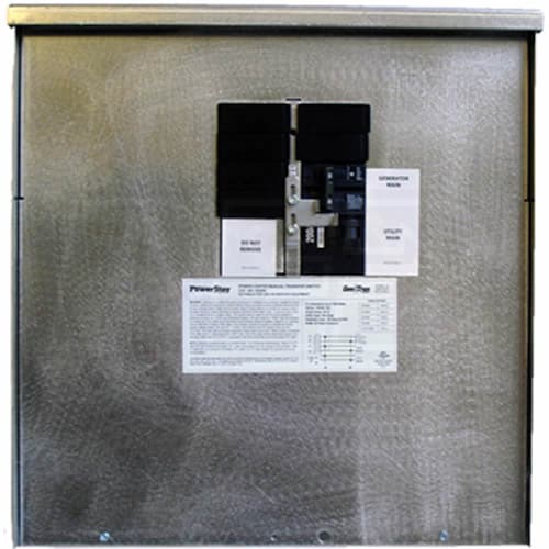
Obviously cannot run my AC on such a small genny, but want to eliminate the trip and fire hazard of using extension cords and use my existing load center.
This is just for "emergency" use during prolonged power outages. We lost power for 10 days from hurricane Sandy.
The generator itself if a gas guzzler and rather load, but it runs like tank. Had some initial issues using it because I was unfortunate enough to get the "new OSHA model" which has GFCI on the 240 outlet.
-JonathanLeave a comment:
-
Just plugged in an older eu2000i into the same step-up transformer, didn't bat an eyelash. my XW inverter qualified the power and shifted loads to it, and started charging batteries.
Likely the quality of the transformer core. my 3.5KVA @ 115# vs outback 30#
Last edited by Mike90250; 07-17-2018, 11:52 AM.Leave a comment:
-
Here's the transformer I use with my champion inverter genset
20180130_110038_TransformerLabel.png
next to the worthless subaru genset (gray box, round decal on top)
20180130_110025.png
a 115# ebay find with free shippingLeave a comment:
-
Well, turns out the water heater element soft start is not perfect. It still over-grunts the generator every now and then if you hit it just at the wrong time when initially starting up the transformer. The neighbor has been running their backup heat pump with it a couple hours a day to keep the house at a comfortable temp, because they're out of wood for heating and it's still getting down into the 30's at night here. And we got too much mud with the snow melt going on for me to haul them a load of wood right now - I'd never make into their place with a truck until the frost goes out.
He told me this morning that he had to try it twice yesterday to get it to "take" because it overloaded the inverter on the little generator the first time.Leave a comment:
-
No changes in frequency here. Those things put out closer to a square wave, than a sine. A square waveOriginally posted by inetdog
is ideal for a rectifier, for DC power supplies & chargers. Bruce RoeLeave a comment:
-
The regulation effect comes primarily from core saturation (well, part of the core anyway) and so in their simplest form they produce a distorted (non-sinusoidal) output voltage. A ferro-resonant voltage regulator/stabilizer with sine wave output cost significantly more to manufacture.
The reliance on core saturation combined with the resonant tank circuit has the unfortunate (for some purposes) side effect that a 1% change in frequency will produce a 2% change in output voltage.Leave a comment:
-
Well ferroresonant transformers are voltage regulators. A basic ferroresonant transformer consists of a core, a primary winding, two secondary windings (one for the load and one for the capacitor) and a magnetic shunt that separates the primary and secondary windings. Th e winding for the shunt with a tuning capacitor form the tank circuit to buck or boost to regulate output voltages.Leave a comment:
-
-
Not that complicated. They have a resonant LC tank circuit which can buck or boost so the output remains constant fixed voltage for short minor power fluctuations. The LC tank circuit can adsorb and give up energy passively. They also have very high common mode rejection ratios up to 160 dB with an electrostatic shield. They do not get used much now days since signal transmission has switched from ground referenced to balanced and optical.Leave a comment:


Leave a comment: