Is welding cable suitable for battery systems?

Collapse
X
 
  • Time
  • Show
Clear All
new posts
  • Mike90250
    Moderator
    • May 2009
    • 16020

    #16
    Originally posted by sdold
    I think the waveguide was about $5 a foot. It's not a waste,it would just go to the recycler anyway. We always add 10 or 20 extra feet when we send out a reel of waveguide for a job because for a 100 or 150 foot run, it's not much more and it would be a disaster for the crew to come up short. It's not silver plated and no flanges used.
    Are you calling helical hardline "wave guide" ? Waveguide is rectangular, has launcher modules to transition from coax to waveguide, and is extremely low loss. Usually thick, precision milled resonant cavity and thick, stiff, inflexible walls, with coupling flanges brazed or welded on, and then the whole works silver or gold plated. It would be a crime to flatten it.
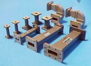
    Just wanting to talk the same terms here. http://www.atmmicrowave.com/waveguide/

    hardline:


    Waveguide:
    Last edited by Mike90250; 06-03-2017, 02:27 AM.
    Powerfab top of pole PV mount (2) | Listeroid 6/1 w/st5 gen head | XW6048 inverter/chgr | Iota 48V/15A charger | Morningstar 60A MPPT | 48V, 800A NiFe Battery (in series)| 15, Evergreen 205w "12V" PV array on pole | Midnight ePanel | Grundfos 10 SO5-9 with 3 wire Franklin Electric motor (1/2hp 240V 1ph ) on a timer for 3 hr noontime run - Runs off PV ||
    || Midnight Classic 200 | 10, Evergreen 200w in a 160VOC array ||
    || VEC1093 12V Charger | Maha C401 aa/aaa Charger | SureSine | Sunsaver MPPT 15A

    solar: http://tinyurl.com/LMR-Solar
    gen: http://tinyurl.com/LMR-Lister

    Comment

    • sdold
      Moderator
      • Jun 2014
      • 1452

      #17
      Those are short rigid pieces that would be use in the vault, looks like some 18, 11 and 6 GHz transitions. I'm talking about the elliptical wave guide that runs from the radio in the vault to the dish on the tower. Long gone are the days of round rigid pipes like the old AT&T sites. It does look a little like the coax you mentioned. The version we use is even called "Heliax", just like the coax.

      ew63.jpg
      Last edited by sdold; 06-03-2017, 03:08 AM.

      Comment

      • bcroe
        Solar Fanatic
        • Jan 2012
        • 5209

        #18
        Originally posted by sdold
        Those are short rigid pieces that would be use in the vault, looks like some 18, 11 and 6 GHz transitions. I'm talking about the elliptical wave guide that runs from the radio in the vault to the dish on the tower. Long gone are the days of round rigid pipes like the old AT&T sites. It does look a little like the coax you mentioned. The version we use is even called "Heliax", just like the coax.
        Cool stuff. As for copper pipe, I read its not the purity of wiring, which considerably degrades conductivity.

        Bruce (less than 1 GHZ) Roe

        Comment

        • Sunking
          Solar Fanatic
          • Feb 2010
          • 23301

          #19
          Mike Microwave Wave Guide is essentially a copper pipe, and not a Coaxial cable. The diameter of the pipe determines the operating frequency. Your picture of hardline coax withe the key is 1-/5/8" 50-Ohm hard-line coax. Technically the same stuff you use with your TV, just much larger. The reason it is so large is to control loss.

          If you look closely at cell towers you will see a lot of it running up the tower. With Today's cellular technology each radio uses 12 Hardlines. There are 4 bands in use today operating at 700, 800, 1900, and 2100 Mhz. So it is very possible you can see 48 hard lines going up a tower and even more if there is more than one carrier located on the tower.

          Having said that coax is going away on cell and microwave radios. Bandwidth demands are antiquating coax. All being replaced by fiber optics. The radio equipment has always been located inside the equipment shelter. That equipment generates a lot of heat and has to be kept cool. All that is going away. How you ask? Real simple, you put the radios on top of the towers with the antennas and use optic cable to bring the signal down. All that is needed in the shelter today is the DC Battery Plant and Transport back to the Switching Office. With the radios on top you avoid the signal loss on the coax, and loose all that heat in the shelter requiring very expensive air conditioning. The radios need DC Power, Optic cable, and some require helium for Cryo RX amps on the lower frequency radios.
          MSEE, PE

          Comment

          • sdold
            Moderator
            • Jun 2014
            • 1452

            #20
            I think Mike posted the coax pictures because he wondered if I was referring to coax. It sounds like he's familiar with this stuff but maybe hadn't seen much of the elliptical waveguide.

            I've seen some of the systems where the radio is on the back of the dish instead of in the vault, but so far for all of our 6 GHz backbones we are keeping the radios in the vault. None of our long haul stuff is made to be on the tower, but some of our shorter 10,11 and 23 GHz paths are that way. I think there are a couple of reasons that it will stay that way for a while. One is the amount of work it takes to fix something in the vault compared to up the tower, especially in storms, night, or when alone. Second is that the waveguide loss is only a dB or two at 6 GHz even on a fairly long run. I guess a third is that cost isn't a concern, Also I've seen some tower-mounted radios generate RFI, so that could be a problem with our VHF receivers.
            Last edited by sdold; 06-03-2017, 10:09 PM.

            Comment

            • bcroe
              Solar Fanatic
              • Jan 2012
              • 5209

              #21
              Originally posted by Sunking
              Real simple, you put the radios on top of the towers with the antennas
              Back to the original designs. Remember the tall concrete towers AT&T put up after the war to carry their
              microwave links across the country? Of course the radios were at the top, right next to the antennas,
              but easily accessible. Later they had to build steel extensions, when they discovered the signal was being
              bent into the ground. Still see one in OH. Bruce Roe

              Comment

              • Sunking
                Solar Fanatic
                • Feb 2010
                • 23301

                #22
                Originally posted by bcroe
                Back to the original designs. Remember the tall concrete towers AT&T put up after the war to carry their
                microwave links across the country? Of course the radios were at the top, right next to the antennas,
                but easily accessible.
                Yes that was what was called Long Haul. You still see a lot of those towers today, but most have been decommissioned. Just about all Central Offices are fiber optic today.

                Just ten short years ago cell towers used copper or Microwave T1 digital. 4G aka LTE did away with all that as it just does not have the bandwidth required. Minimum requirement to day for just 1 radio is 100 mb.\/s Gigabit Ethernet. Microwave radio is pretty much limited to 183 mb/s bandwidth and only good for spur shots off a Ring. Verizon Wireless now uses Fiber Rings using 10 bg/s ethernet. and drrops/inserts 100 to 300 mb/s to each cell site.

                The largest site I have seen is Cowboy Stadium in ?Arlington TX. Verizon alone goes in with 1 Gig Ethernet and runs 7 radios inside the stadium. Ironically the place is called ATT stadium and ATT only has about half the capacity as Verizon with 4 radios. Then you have Sprint, T-Mobile on top of that. Fans have no clue they are being cooked with radio in just about any stadium today. In stadiums they use 1900 and 2100 Mhz radios which is roughly the same frequency a microwave oven uses. Just Verizon alone if you add up all the radios power is on the order of 1200 watts. Add all the cariers up and you are looking at just shy of 3000 watts of RF exposure confined to a small area.

                MSEE, PE

                Comment

                • sdold
                  Moderator
                  • Jun 2014
                  • 1452

                  #23
                  I'm not too worried about microwaves, you could stand in front of one of our 6 GHz long-haul transmitting dishes all day long. The transmitters are only one watt.

                  Comment

                  • bcroe
                    Solar Fanatic
                    • Jan 2012
                    • 5209

                    #24
                    Originally posted by sdold
                    I'm not too worried about microwaves, you could stand in front of one of our 6 GHz long-haul
                    transmitting dishes all day long. The transmitters are only one watt.
                    Perhaps, but that is a very idealistic link. If there are hundreds of conversations (or lots of bandwidth) going on, each likely
                    will add its signal to the output of the final linear, and not with the efficiency of a point to point link. All the phones answering
                    back will add their energy to the soup. Although, normally I'd expect radiation from your own phone to be the worst case
                    trying to operate in an elevator, basement, or FAR out in the country. Bruce Roe

                    Comment

                    • sdold
                      Moderator
                      • Jun 2014
                      • 1452

                      #25
                      How far do you think the cell site transmitters might be from the people? It might be fun to estimate this.

                      Comment

                      • bcroe
                        Solar Fanatic
                        • Jan 2012
                        • 5209

                        #26
                        Originally posted by sdold
                        How far do you think the cell site transmitters might be from the people? It might be fun to estimate this.
                        In the case of the stadium, might be on the order of 150 yards. Power, so variable, better find a way to measure it. Bruce Roe

                        Comment

                        • sdold
                          Moderator
                          • Jun 2014
                          • 1452

                          #27
                          We can assume it's a typical 50 watt RRU. How many do you think there might be? A couple per carrier per sector, maybe three carriers, for six per sector, does that sound reasonable? I'll assume 10 dB antenna gain.
                          Last edited by sdold; 06-04-2017, 06:12 PM.

                          Comment

                          • bcroe
                            Solar Fanatic
                            • Jan 2012
                            • 5209

                            #28
                            Feel free to make estimates. I expect thousands of phones might be active during a break in the game. Poke
                            an untuned probe in there and watch over the duration. Bruce Roe

                            Comment

                            • sdold
                              Moderator
                              • Jun 2014
                              • 1452

                              #29
                              Sunking estimated 3 kW for everything, which sounds pretty reasonable. I'm curious too. I'll make a quick estimation based on that and 10 dB gain. Luckily with that many local carriers the phones would be running low power.

                              EDIT: I doubt too many people are interested at this point, but since it came up: With OET-65 equation 4, which I think applies, using 30 kW EIRP and 150 meters from the transmitters, I get 0.01mW/cm^2, which is about 1/10 of that allowed in appendix A, Table 1, the FCC exposure limit for the general public. So I wouldn't worry about being there as far as the cell sites go. I've only done two MPE on-site surveys and only one was at a site that included a few carriers, but this is about what I remember seeing.

                              I don't know what kind of numbers adding up the power of the phones would give you. It would be interesting to try to figure it out.
                              Last edited by sdold; 06-04-2017, 07:44 PM.

                              Comment

                              • Sunking
                                Solar Fanatic
                                • Feb 2010
                                • 23301

                                #30
                                Originally posted by sdold
                                I'm not too worried about microwaves, you could stand in front of one of our 6 GHz long-haul transmitting dishes all day long. The transmitters are only one watt.
                                Ture but a 6-ft dish is 2 degree beam width and 20 to 30 Db gain. 1 watt 30 db is 1000 watts ERP. I know from personal experience what happens if poking around trouble-shooting MW radio you tough the output. You get a nice little puff of smoke and a white spot of ash on your finger and cuss like a drunk sailor for being STUPID. I was smart enough only happened once. I learned that at age 17


                                MSEE, PE

                                Comment

                                Working...