No it is not needed, just very handy to have. If you make a JST Balance Plug and cut-off one of the keys, you can make it work. Just one wrong, connection or mistake, and you let the SMOKE out of the charger.
-
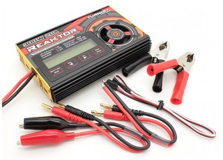
The "balance board" is not needed as it is built in to the Reaktor. The balance board just splits one balance port connector up to several different size connectors so you can plug prebuilt batteries that have a different size balance connector dependant on how many cells there are in the battery.
I think your best bet is to get a premade cable assembly something like this, cut off the male connector and wire the individual wires to the cells.
Simon
Off grid 24V system, 6x190W Solar Panels, 32x90ah Winston LiFeYPO4 batteries installed April 2013
BMS - Homemade Battery logger github.com/simat/BatteryMonitor/wiki
Latronics 4kW Inverter, homemade MPPT controllerLeave a comment:
-
Page 11 of the manual (page 13 of the pdf i uploaded) gives the pinout for connecting LFP cells for balance charging directly to the charger (via its balance port). There is no mention of needing a balance board. Am i being ignorant here? Sounds like i just need to make the correct connections. I believe i read a customer review which mentioned not needing balance boards, too.
Of course, the manual is written in broken english (not the worst ever, but not the best)...so i'm not exactly going to take that one page as gospel. It would be nice if, for example, they gave some indication what type of connector i need, to build my balance-charging pigtail. I guess i'll just browse through a helicopter forum until i figure it out.
The iCharger was an attractive option but, like every other charger i saw except the Reaktor, it only operates on ~12VDC input. The built-in AC-->DC power supply of the Reaktor is important because space matters more to me than probably a lot of other folks. A separate power supply is yet another box to find a place for.
With electronics especially, i'm skeptical of all products - both imported and domestic. But automatically dismissing all Chinese imports as junk is kinda behind the times. As sensij mentions, i am aware that a lot of products roll off the exact same lines and just get boxed or branded differently. It's hard to have confidence in the country-of-origin of just about anything anymore. So i'm fine with imported goods but i do check reviews first (and do silly things like ask around on forums).Leave a comment:
-
From the site you linked:
icharger.co.nz distributes products from www.jun-si.com. Sure, that sounds like an authentic New Zealand company to me, too. The iCharger and Reaktor are probably produced in the same factory, or at least were at one time, just like the equivalent models from Thunder, Voltz, NeuEnergy, etc.Please Note: The iCharger 1010+ standard package does not include a balance board. Compatible JST-XH, Polyquest, Hyperion or Thunderpower balance boards are available separately.
Edit again: Here is a 2000+ post active thread in which the Reaktor is thoroughly dissected, compared to other chargers, etc.Last edited by sensij; 10-31-2017, 12:28 PM.Leave a comment:
-
That is what you get for listening to Karrak. What you bought is Counterfeit Chi-Com Junk. It is stolen property from New Zealand.Exactly what Karrak sells and promotes here. He rips off his own country's companies. It is a Counterfeit Copy of an iCharger 1010B. Did they even give you the Balance Board shown with the iCharger in the pic below? Now if you want a good copy of the manual, try the real thing, not a fake.
When it comes down to it, the iCharger 1010B is a scaled down version of the PL8. the difference is the iCharger can charge @ 300 watts max, while the PL8 can charge @ 1330 watts or 4.4 times faster. The charger is great for smaller batteries used in RC planes, Quads, and Trucks. (does toys come to mind).For 12 volt batteries you are limited to about 200 AH and 100 AH @ 24 volts. PL8 up to 1000 AH at 12 volts and 500 AH @ 24 volts.
Last edited by Sunking; 10-31-2017, 11:47 AM.Leave a comment:
-
You don't have to convince me; i was about to pull the trigger on an Orion BMS the day i found this forum, but posts by you and others convinced me the Orion would have been money badly spent.We ripped out the BMS and sold them
Frankly, at the moment i don't...but that doesn't mean i enjoy wasting time. Thanks for the better suggestion.That will work if you have no life and no one cares about you.
Oh, and since this thread is supposed to be about cell chargers:
I scanned in the Turnigy Reaktor 300W manual, in case someone else is looking for it. The quality is low for filesize, so the text is pretty fuzzy. Sorry about that.
Leave a comment:
-
That will work if you have no life and no one cares about you. I certainly don't care. You discharge than all in series until the first battery is drained. Note AH. Now discharge the last cells and count AH. Should not take more than 2 hours of your time and not days.
[Mod note - deleted spam]
You are right, the weakest cell determines the pack capacity. So how do you stop or correct that problem, Just one little mistake or a Vampire/Montitor board fails and you will destroy a cel. BMS systems are the number 1 cause of LFP failures. Us folks in the EV field learned this hard lesson long ago. We ripped out the BMS and sold them. When you Bottom Balance, you eliminate any chance of over discharge. All cells have the same capacity and thus all arrive at 2.5 volts at the same time making it impossible to drive a cell into reverse polarity.
Where did we learn about Bottom Balance? NASA, Boeing, Hughes Aircraft, Lockheed Martin, and Saft Battery Manufacture. Those companies use LFP and lithium batteries in mission critical systems, mainly satellites that orbit the earth. They do not Top Balance or even use a BMS in the sense you are thinking. They like all EV manufactures Middle Balance. Bottom Balance mimics Middle Balance where the cells are never allowed to be fully charged or discharged, they stay in a Partial State of Charge until the satellite falls out of orbit and burns up on reentry.
[Mod note - deleted spam]
Moderator Note - Forum spam consists of posts on Internet forums that contains related or unrelated advertisements, links to malicious websites, trolling and abusive or otherwise unwanted information.Last edited by sensij; 10-31-2017, 12:34 PM.Leave a comment:
-
I shouldn't rely on my memory but I remember calculating the battery and interconnect resistance of my battery at around 6mOhms. Going from charging at around 10A to discharging at around 80A drops the overall battery voltage by about a volt.
It might be worth going round the system with a multimeter and measuring the voltage drops across the interconnects, lengths of cable, fuses and circuit breakers individually when there is a high discharge current to get an idea where the losses are occurring.
Simon
Off grid 24V system, 6x190W Solar Panels, 32x90ah Winston LiFeYPO4 batteries installed April 2013
BMS - Homemade Battery logger github.com/simat/BatteryMonitor/wiki
Latronics 4kW Inverter, homemade MPPT controllerLast edited by karrak; 10-29-2017, 05:16 AM.Leave a comment:
-
And when someone is abrasive, verbose, and prone to 'personal attacks', doesn't mean they should be ignored.
Everything here is "something i read on the internet" and i treat it as such. My LFP bank is my experiment and my responsibility. Since there is no true authority on the subject to defer to, this is more like politics than engineering. Who to trust? Make small changes, measure the results, and make data-driven decisions.
If you this forum has a lot of misinformation mixed in...take a look at diesel truck forums! OMG.Last edited by zamboni; 10-28-2017, 08:53 AM.Leave a comment:
-
just remember, when someone is vocal, verbose, and saying stuff thats easy to hear, does not make that person correct.Leave a comment:
-
I tried to find all the existing LFP posts using searches, but i'm sure i missed something. This forum is basically the only place anybody is talking about the "nuts and bolts" of LFP for renewable energy, which makes it a goldmine. But i have to say -- moreso than most other forums -- the content of the threads diverges wildly from the topic of the thread in most cases. It can be an ordeal as a newcomer ; ) It's a treasure hunt that pays off, though.I wonder how much of the other threads you have waded through! Like trying to wade through molasses.
You are correct about remotely stopping the Classic, however i will be adding the Whizbang Jr. Module (for accurate voltage measurements at the shunt instead of at the Bat+/- terminals of the charger). And the WBJ inputs to the Classic via Aux2 -- the same port used to drive the Classic to rest/float/charge externally. So i have to choose. The WBJ will make the shunt-measured voltage available to the Classic for all voltage-based decisions, so i definitely want that. Adding the cellog may be a little redundant, but i can parallel its outputs with the JLD to give both pack-level and cell-level HVD protection, and should not really get nuisance trips from the lack of hysteresis, since the HVD operating point will be several tenths of a volt above my charge voltage.Again I am fairly sure that this can be used to stop the Midnite. One problem with the Cellog 8s is that there is no hysteresis between the alarm being On or Off. In this case the cellog 8s are your BMS.
Also, it will let me keep an eye on cell voltages without having to remove the toilet and open the panel in the floor...
Only briefly. DIY electronics are definitely on my project-fun list...but pretty close to the bottom. I'm a mechanical engineer with enough familiarity with electronics to wire a house or (apparently) set up a small, simple PV system...but a long way from being an electronics hobbyist. Also, i have been spending far too much time with projects and not enough time outside, which is the whole reason i moved into a damn RV in the first place ; ) So i'm trying to limit my "project fun-time" to just the stuff that keeps the rig rolling (am having some truck issues too, at the moment).Have you had a look at my BMS?
The new charger and cellog will give me plenty to play with during rainy days, anyway. If i can't figure out how to plot the logged Reaktor data myself, i'll hit you up for help.
My cell interconnects follow the same regime as your diagram...except 5p4s. The connections are just 2-hole bars, from one cell to the next, and overlapping at each terminal. It's not elegant. I don't have the equipment to accurately measure the resistance of a single interconnect, but would not be surprised if they were a problem. A crude deltaV / deltaI calculation from the Magnum control panel (turned off everything in the trailer then turned on a 1500W inverter load), and came up with Ri ~ 4mOhm. This doesn't seem awful to me, but i'm still looking at nearly a full volt of sag when i fire up the water heater or electric teakettle, so i'm interested in improving it. The fundamental problem is that the whole system really ought to be 24V...but i won't be changing that anytime soon. Better interconnects may help. I would love to get multi-hole braided bus bars custom made for my pack, so i don't have overlapping bus bar at each terminal, but i'm not sure if now is the time. I'll look into the link you sent and see what they can make at what price.I would have a good look at the interconnects as your Inverter could draw over 300A from the battery. I ran some SPICE simulations on the wiring arrangement I outlined earlier and found that the resistance of the interconnects need to be less than 1/10 the cell resistance to get good current balance. Is that wiring arrangement the same as how you currently have your battery wired up?
Leave a comment:
-
I agree with you that you only need to have the battery balanced at the voltages that you will be charging to. Makes it a hell of allot easier than having to do a special balance procedure at voltages that you would not usually use. Only exception to this would be that I think it is worth doing the initial commissioning balance at around 3.6V as this will give an even tighter balance at the voltage that you intend to charge to on a regular basis.
I wonder how much of the other threads you have waded through! Like trying to wade through molasses.
As you say you could use one cellog 8 to generate the LVD. I am fairly sure that there is a remote OFF input on the Magnum that this could be fed into. On the charger side another cellog 8 could be used to generate the HVD. Again I am fairly sure that this can be used to stop the Midnite. One problem with the Cellog 8s is that there is no hysteresis between the alarm being On or Off. In this case the cellog 8s are your BMS. Have you had a look at my BMS?Originally i thought i could skip the BMS. If i had bought better cells, i probably could (as you imply above), but watching individual cell voltages just with my meter has shown me that my cells are too unruly and i need cell-level monitoring. I caught one string shooting up very quickly once, and that got my attention. We leave the trailer unattended quite a lot when we go out for a day -- i don't want to come home to a plasma ball. So i just bought a cellog. With the whizbang jr. connected to the Classic and "high" balanced cells, i should be able to count on the classic keeping cell voltages under control by measuring pack voltage, and the JLD can throw the overcharge protection solenoid if pack voltage creeps up beyond that. But the cellog can watch cell voltages on the discharge end, and throw the LVD if any cell gets too drained.
I supposed i could use a second cellog to manage the overcharge protection too...then i wouldn't even need the JLD, or a BMS. But i'm trying to avoid throwing money/complexity at this system. The cellog is worthwhile because i otherwise have no realtime monitoring of cell voltages. And it's really inexpensive.
Yes that is how I generated the graphs. There are a few tricks to processing the data. If you decide to generate your own plots I can give you some tips.Did you create these from logged data in the Reaktor?
Sound like a good strategy to me.I agree that with the correct setup, coulomb counting can be a very useful tool. But people always get bent out of shape on public forums if you give any hint that you think a $15 "fuel gauge" is useful. So i just err on the extreme side of things and pretend that i'm not going to pay much attention to SOC. But in reality, that's the number i look at the most. I only pay attention to other numbers if something seems wrong with SOC. The system's automated controls are built around voltages, but for a user-facing interface SOC% is much more intuitive.
I would have a good look at the interconnects as your Inverter could draw over 300A from the battery. I ran some SPICE simulations on the wiring arrangement I outlined earlier and found that the resistance of the interconnects need to be less than 1/10 the cell resistance to get good current balance. Is that wiring arrangement the same as how you currently have your battery wired up?Didn't take it that way. Grateful for the link! Upon disassembly i may decide i'm unhappy with my non-braided bus bars. My first choice was braided, but we were rushed when we did the initial conversion to LFP so i didn't source any.
Simon
Off grid 24V system, 6x190W Solar Panels, 32x90ah Winston LiFeYPO4 batteries installed April 2013
BMS - Homemade Battery logger github.com/simat/BatteryMonitor/wiki
Latronics 4kW Inverter, homemade MPPT controllerLeave a comment:
-
Inconceivable!I think you will find that battery balancing is not as big an issue as it is made out to be.
I've come to regard cell balancing as choosing the voltage at which you want to be able to rely on whole-pack voltage (rather than separate cell measurements) to make decisions. Even "top" and "bottom" are misnomers because i expect a well-informed user would dial their voltages away from the very ends of the knees anyway. It's more like "high" and "low" balancing... I'm shooting for "high" for all the reasons already established in other threads: Solar charged, low-C, many days of reserve capacity.
...It is easier to start off with a battery that is balanced but if you have some sort of cell monitoring and alarm or even better a BMS that will shut down the charger or loads
Originally i thought i could skip the BMS. If i had bought better cells, i probably could (as you imply above), but watching individual cell voltages just with my meter has shown me that my cells are too unruly and i need cell-level monitoring. I caught one string shooting up very quickly once, and that got my attention. We leave the trailer unattended quite a lot when we go out for a day -- i don't want to come home to a plasma ball. So i just bought a cellog. With the whizbang jr. connected to the Classic and "high" balanced cells, i should be able to count on the classic keeping cell voltages under control by measuring pack voltage, and the JLD can throw the overcharge protection solenoid if pack voltage creeps up beyond that. But the cellog can watch cell voltages on the discharge end, and throw the LVD if any cell gets too drained.
I supposed i could use a second cellog to manage the overcharge protection too...then i wouldn't even need the JLD, or a BMS. But i'm trying to avoid throwing money/complexity at this system. The cellog is worthwhile because i otherwise have no realtime monitoring of cell voltages. And it's really inexpensive.
20 cells here...not as big a task as you, but not trivial either! I had to drill and tap all 40 terminals in order to build the pack in the first place and that was pretty tedious. I can be patient and deliberate if it suits me : ) I'm ever so grateful for the advent of podcasts; making tedium infinitely more bearable.I agree that it is good to know what the capacity of the individual cells is before you start. If I had had the Reaktor before I commissioned my battery I would have done a capacity test. I would have probably done it on only a few cells as it would be allot of work and take some time to do the 32 cells that I have!
I seem to be a suck-magnet most of the time, so i'm planning on bad news. But maybe not!I would be very surprised if you find the variation between cells to be more that a couple of %.
Did you create these from logged data in the Reaktor?Here are the charge/discharge curves that I did for one of the cells from my friend's system...
I have the manufacturer's published charge/discharge curve and i'm curious to compare it with my cells' actual performance, if i have time.
I agree that with the correct setup, coulomb counting can be a very useful tool. But people always get bent out of shape on public forums if you give any hint that you think a $15 "fuel gauge" is useful. So i just err on the extreme side of things and pretend that i'm not going to pay much attention to SOC. But in reality, that's the number i look at the most. I only pay attention to other numbers if something seems wrong with SOC. The system's automated controls are built around voltages, but for a user-facing interface SOC% is much more intuitive.I think you will find that the measured SOC using the current flow too/from the battery will be more than a convenience as it can be accurate to within a few % if you adjust the reading to take into account the ~0.5% coulomb/current inefficiency of LFP batteries. It is far harder to work out the SOC from the battery voltage.
I plan something similar with my Trimetric, which is what's visible in the living space.I have set my SOC counter to read 0% when there is 10% of the rated capacity left in the battery and it resets to 100% every time the average cell voltage is 3.45V with a charge current of less than C/20
Didn't take it that way. Grateful for the link! Upon disassembly i may decide i'm unhappy with my non-braided bus bars. My first choice was braided, but we were rushed when we did the initial conversion to LFP so i didn't source any.Sorry, it wasn't intended to be an advert.Last edited by zamboni; 10-27-2017, 07:50 AM.Leave a comment:
-
I think you will find that battery balancing is not as big an issue as it is made out to be. It is easier to start off with a battery that is balanced but if you have some sort of cell monitoring and alarm or even better a BMS that will shut down the charger or loads if any individual cell goes out of its safe operating voltage range you can't run into any problems. I know this from experience. When I purchased my battery I didn't have any equipment to balance it so paid the battery supplier to balance it. This was not done properly so I soon had a problem during the night where one block of paralleled cells dropped below 2.8V. The Cellog 8 that I had as my first BMS gave an audible alarm which woke me up and I turned the inverter off. As this is my house power supply and I live in the country it was easier to balance the battery while it was in use rather than disassemble it and make arrangements to get the cells individually balanced. I still make minor adjustments to the balance every now and again while the battery remains in use. Rather than the procedure that I stated earlier I just look at the maximum daily variation in voltage between the cells which is logged by my BMS and if it gets to more than 0.05V I will either remove or put a fixed amount of charge into the high/low cells by either putting a 1 Ohm resistor across the high cells on charging the low cells with a bench power supply for a fixed amount of time.
Having built our own house I know what you mean by learning on the job, at least you are now an expert, the second one will be easier
I agree that it is good to know what the capacity of the individual cells is before you start. If I had had the Reaktor before I commissioned my battery I would have done a capacity test. I would have probably done it on only a few cells as it would be allot of work and take some time to do the 32 cells that I have!Another reason i was planning to do this cell-by-cell; i want to measure each cell's capacity starting from my operating "full" voltage (that its, voltage i will balance them all to, eg. 3.5vpc). I think i can only do that by individually discharging each cell. My motivation is -- if i'm getting this right -- that the smallest individual cell's capacity will drive my entire pack's effective capacity. If my weakest 200Ah cell nets 160Ah between 3.0 and 3.5vpc, then my whole pack's usable capacity (over that same voltage range) is 800Ah. I want to know this capacity so i can reprogram the Trimetric and have the SOC feature read out the full range of usable capacity only, from 0-100%. I know SOC is only a convenience gauge. But i'm not the only user of the system and it needs a few user-friendly features.
As I am running four cells in parallel and each set of four cells was picked randomly I would think that any variation in the cells would be balanced out across the four cells so the capacity of the battery will not be so dependent on the capacity of the weakest cell. In your case if you measure the capacity of each cell you can make up the blocks of five parallel cells so that each block has roughly the same capacity. I would be very surprised if you find the variation between cells to be more that a couple of %.
Here are the charge/discharge curves that I did for one of the cells from my friend's system. I would think the curves for your cells will be similar. This will give you an idea what your 3.0V to 3.5V voltage range will mean in terms of SOC at different currents.
I think you will find that the measured SOC using the current flow too/from the battery will be more than a convenience as it can be accurate to within a few % if you adjust the reading to take into account the ~0.5% coulomb/current inefficiency of LFP batteries. It is far harder to work out the SOC from the battery voltage. I have set my SOC counter to read 0% when there is 10% of the rated capacity left in the battery and it resets to 100% every time the average cell voltage is 3.45V with a charge current of less than C/20
Not sure if you have seen this version of the manual media3.evtv.me/JLD404AH.pdf which is an improvement on the original. Yes I am referring to the "APuL" entry.My JLD404 is actually branded "ECPC404". I'm pretty sure it's identical to the JLD but it came with scant documentation. I found some JLD stuff online though...is the offset you're referring to the "APuL" entry in the "0036" menu? It's a capable little meter but man, what an appalling interface!
YesRegarding the "Ah reset switch"...the only such switch i'm aware of is the "down arrow" button, which must be held for ~3 seconds. Is that what you're talking about?
Sorry, it wasn't intended to be an advert. I just picked that link because it shows what braided links are. If you are putting the five cells in parallel it is most important that you make sure that the links all have the same resistance and follow the guidelines in the article that I gave a link too earlier to make sure the current is shared equally between the cells.I'm taking this under advisement. The pack is assembled with the laminated bus bars that came with the cells, using star-lock washers. Star locks held their torque very well on my old FLA bank, but these joints are different geometry. I'll be paying attention to the break-loose torque when i take it apart, and will decide about braided ties & nordlocks at that point.
Simon
Off grid 24V system, 6x190W Solar Panels, 32x90ah Winston LiFeYPO4 batteries installed April 2013
BMS - Homemade Battery logger github.com/simat/BatteryMonitor/wiki
Latronics 4kW Inverter, homemade MPPT controllerLeave a comment:
-
Well, i have the Reaktor in front of me; it arrived today (HobbyKing ships appallingly fast). The unit can be indeed be powered from either 12VDC source or AC mains, and the manual does state that regenerative discharge is available back thru the 12VDC connections. I won't get around to actually using this charger on my house bank for a while (have to wrap up another big project first), but i'll try to test the regeneration feature when i do.Other thing that would be worth confirming is if you can do regenerative discharge back into a battery connected to the AC unit. It looks like you can as there is a DC input on the unit.
That does sound faster! As for your other suggestions -- i'm going to keep copies in case i'm ever stuck with a balance issue and no access to shore power. But one advantage of an RV is that it's portable. I consider it easier to just get the rig to shore power and start over from scratch with the pack, rather than trying to wrangle it back under control while still remaining (mostly) online, as i believe you are suggesting. Partly this is just my personal comfort level, partly i know i need to improve my interconnects anyway, and partly access to my pack is very poor. I made a huge mistake by tucking it into a tight spot, and am consequently planning to cut a trap door into the bathroom floor so i can get better access to the tops of the cells! I've definitely made plenty of mistakes with my RV's system, but the money is spent. I've learned a lot since then, and i'm making the best of it.Rather than charging all cells to around 50% then charging each one individually with the Reakor you could charge them all in series (4p5s or 5p4s) with the Reakor using the balance charge function with the balance leads connected. When the first cell reaches the set charge voltage you could then put all the cells in parallel and charge them up to whatever voltage you want to balance them at. This will be much faster.
Another reason i was planning to do this cell-by-cell; i want to measure each cell's capacity starting from my operating "full" voltage (that its, voltage i will balance them all to, eg. 3.5vpc). I think i can only do that by individually discharging each cell. My motivation is -- if i'm getting this right -- that the smallest individual cell's capacity will drive my entire pack's effective capacity. If my weakest 200Ah cell nets 160Ah between 3.0 and 3.5vpc, then my whole pack's usable capacity (over that same voltage range) is 800Ah. I want to know this capacity so i can reprogram the Trimetric and have the SOC feature read out the full range of usable capacity only, from 0-100%. I know SOC is only a convenience gauge. But i'm not the only user of the system and it needs a few user-friendly features.
My JLD404 is actually branded "ECPC404". I'm pretty sure it's identical to the JLD but it came with scant documentation. I found some JLD stuff online though...is the offset you're referring to the "APuL" entry in the "0036" menu? It's a capable little meter but man, what an appalling interface!You can set a small positive current offset in the calibrate menu to make the JLD404 Ah counter take account of the coulomb/current inefficiency of the battery. The Ah counter offset is calibrated correctly when the Ah counter is zero when the charger switches to float. You can also get the JLD404 to automatically reset the Ah counter when the battery is fully charged by soldering some wires to the Ah reset switch (I can't remember which switch it is) and connecting it to the relay output of the JLD404 and set the relay to operate when the battery reaches the fully charged voltage.
Regarding the "Ah reset switch"...the only such switch i'm aware of is the "down arrow" button, which must be held for ~3 seconds. Is that what you're talking about?
Yes, i think i should. I want something (besides just me and my Amprobe 560) monitoring my cell voltages. It's certainly an affordable device.I would get a Cellog 8 to monitor the individual voltages and set an alarm voltage of 3.65V. This will give you plenty of warning.
I'm taking this under advisement. The pack is assembled with the laminated bus bars that came with the cells, using star-lock washers. Star locks held their torque very well on my old FLA bank, but these joints are different geometry. I'll be paying attention to the break-loose torque when i take it apart, and will decide about braided ties & nordlocks at that point.A number of us use braided interconnectionsLeave a comment:


Leave a comment: