
While I don't think this referenced thread provides any hard data, and much of the headline is buried since the diagrams are apparently broken in it, I do think there is merit in being concerned about parallel strings having load imbalance issues. However, my back-of-the-envelope calculations suggest that there is enough lossy resistance in the interconnect (fusing, contactors, lugs, wire) to make the current division pretty minimal across a set of six or seven large strings. It's possble, though, that some degree of wear leveling may be warranted at some point.
There are lots and lots of paralleled banks in commercial, engineered LFP packs (and in tons of EVs). These seem to do okay? They benefit from state estimation in each module ("string") but, nevertheless, I have no doubt that they experience some uneven wear over time.
-
-
Right, in that sentence I was referring to the need to manually verify balance on an occasional basis. Like, once every few cycles for a while, and then every dozen, and then hopefully once a quarter or twice a year or something.
Yeah, I figured it could be rewired. And it's cheap and might even be reliable, but it doesn't exactly engender confidence when you see how it's sourcing its energy.The cellog8 has balanced draw if you modify it so that it is powered by an external power supply.
For the graph you included, is this a bottom-balanced set of cells? Because that's pretty much what mine look like, too. Notice how all your cells are super close in voltage right before you reach CV? How about I just set up the charging logic to never go into CV? I can still set a HVD or charge-terminate relay at the pack voltage where I see the worst cell get up to 3.6V or so, but I don't even think I need to go that far. My minimum acceptable capacity is 25kWh, and this pack is capable of at least 40% more than that at the outset.
Leave a comment:
-
thanks for the link; while I didn't find much details in there about why parallel LFP strings would wear out quicker I found interesting external link there: http://www.smartgauge.co.uk/batt_con.html It considers effects of the way batteries wired in parallel on the amount of current they pass. As author rightfully notes in low internal resistance applications resistance of the wires between batteries becomes comparable to the internal battery resistance leading to significant imbalance of currents flowing through parallel batteries. Ideally all batteries would need to be connected to the load points with individual wires of the same length. With LFP cells lower Ri this is x10 times more applicable so OP might want to take a look there.Leave a comment:
-
I'm currently evaluating Victron Quattro 48/15000/200/100-100. That decodes to 48vdc nominal, 15kva inverter, 200a charger, dual 100a AC feed-through. I believe it has the exact same programmability as all of the Quattros and perhaps the Multipluses as well. Which is to say, less every day, because they seem to be removing features from the software year over year.
I am not wedded to this device, but I like the general modularity and flexibility of the Victron line.
I think I read this discussion too, somewhere. I'll have to go look it up and see if there's more to learn from his experience. I don't find it hard to imagine that a cell might do something like that at some point, but I'm also expecting that it will happen gradually and that I'll be able to observe the side effects of it with careful monitoring. It's possible that I'm wrong on one or both of those expectations.The problem I see with this is that the problem cell in five years time might be a good cell at the moment. I know of one case from a knowledgeable and credible poster on the Australian Energy Matters forum of a CALB cell loosing around 25% of capacity after about three years of use. It was his BMS that picked this up. I have not heard of any cases of cells developing internal short circuits without being abused beforehand.
Like you, I'm less concerned about catastrophic shorts. Were one to occur, though, the parallel-then-serial topology makes that pretty exothermic without cell level fusing.
We just don't hear about many of these, so I have to conclude that they're uncommon and/or benign. I'm inclined not to chase this small risk too hard; there are plenty of other things I could do to improve my expected lifespan that would be easier.
And have you seen a complete failure? Could you also comment on the general type of work you've needed to do and at what frequency?With the two systems I am responsible for which are organised with cells in parallel and then is series I have found that I only have to turn the system power off for a few minutes if I need to do any work on the battery. Even if you have the complete failure of one cell in the battery it would still work but with a reduced capacity.
I'm surprised this is so challenging. Maybe I'm being too blase about this SOC thing, but if I'm not planning on running from 0 to 100 (or anywhere close to either of those boundaries), ever, then I feel like I have a ton of room for slippage, even though on top of that we observe very little in real packs where I have seen data. Heck, I'll barely even get these cells out of their linear regime, it seems like.The main reason I don't like bottom balancing for off-grid systems that are in constant use is that the only way you know if the battery has stayed in balance is to empty it. This might be fine for a EV sitting in a garage for the majority of its life but is not very practical for systems in use all the time. If you top balance you know every time you charge the battery if it has stayed in balance. By charging the battery to nearly 100% you can also easily and accurately reset your SOC meter. I have found my coulomb(current) counting SOC meter is the most useful way of measuring the state of my battery and allows me to plan my energy usage.Last edited by nebster; 09-20-2017, 12:44 AM.Leave a comment:
-
Cell imbalance only shows up when the battery is nearly fully charged or discharged, so you will have to wait for the right time and them take 112 readings. The cellog8 has balanced draw if you modify it so that it is powered by an external power supply.
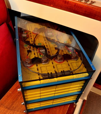
BalVolts&ChargeCurrent.jpg
Simon
Off grid 24V system, 6x190W Solar Panels, 32x90ah Winston LiFeYPO4 batteries installed April 2013
BMS - Homemade Battery logger github.com/simat/BatteryMonitor/wiki
Latronics 4kW Inverter, homemade MPPT controller
Leave a comment:
-
I agree with every word you wrote, and by the way, it also must be the case that this is true at the cell level with parallel-then-serial. In the latter the failure modes do manifest somewhat differently.
The question, though, is how much imbalance and when failure? If it's gone pear-shaped after ten charge cycles, that's a total suck and a non-starter. If it takes 300 cycles, I'll gladly do some checkpointing and swap cells if needed between strings a few times a year. (It's easy to do with my topology!) If it takes 1000 cycles, I'll be nearly dead by then and don't care too much.
I get that debate can be tiring, and I truly appreciate your good intention to warn me... but, really, I'm mostly interested in data. Can you point us to some? It sounds like there is some maybe even stored away in your own brain/build logs!With all the cells at your disposal, you can prove it to yourself by building a learner-bank the wrong way. Watch what happens. I have.
...
I'm just trying to save you some time, effort, and money. Although quite a few of us just don't have the energy for the endless debates any more.
The limited set of applicable data I have been able to source suggests that the imbalance will be manageable. My own crude mathematical model also suggests that it should be doable. I would be happy to be proven wrong before I torque another 224 nyloc nuts.
Leave a comment:
-
Can you tell us the make and model of all the equipment you will be charging your battery with and the different charge rates you will be using, is solar anywhere in the mix?
The problem I see with this is that the problem cell in five years time might be a good cell at the moment. I know of one case from a knowledgeable and credible poster on the Australian Energy Matters forum of a CALB cell loosing around 25% of capacity after about three years of use. It was his BMS that picked this up. I have not heard of any cases of cells developing internal short circuits without being abused beforehand. As far as I am aware (beware I am not an electrochemical engineer) the two ways that cells can develop internal short circuits areWhat do you think about only monitoring a handful of the "troublemaker" cells? So far it seems completely consistent: the same couple cells are the ones with presumably the least capacity, so they spike up much earlier than the rest. I'd really like to avoid rigging up 100+ monitoring circuits if I can help it.- Cell being badly over discharged which results in the copper current collector which is part of the battery cathode being oxidised. If a cell in this state is then charged up again the copper can be reduced back to copper but instead of the smooth copper sheet that it was it can grow pointy copper crystals that can grow between the cathode and anode and eventually short the cell out. These crystals (dendrites) do not have a zero electrical resistance. If there is enough energy in the cell with the dendrite and other cells in parallel and the dendrite resistance is low enough the dendrite will be vapourised and hopefully remove the short. A more dangerous scenario is if there is not enough energy to vapourise the dendrite but enough to heat it up to the point where the other components in the cell around the dendrite start to decompose and add to the heat output. Another issue that could cause problems is that the resistance of the sections of the copper current collector that have been eaten away by the oxidation could become high enough to cause these sections to heat up enough to cause other parts of the cell to decompose.
- Cell being held at a high SOC and high voltage for a long period of time which can lead to lithium dendrites growing from the anode. This takes some time and I don't think is as likely to cause a catastrophic failure of the cell.
I think it is far more likely that over the ten plus years lifespan of the battery that the chance you will get a cell overcharged or over discharged because of changes in individual cell capacities relative to each rather than problems with any cell spontaneously short circuiting.
With the two systems I am responsible for which are organised with cells in parallel and then is series I have found that I only have to turn the system power off for a few minutes if I need to do any work on the battery. Even if you have the complete failure of one cell in the battery it would still work but with a reduced capacity.
The main reason I don't like bottom balancing for off-grid systems that are in constant use is that the only way you know if the battery has stayed in balance is to empty it. This might be fine for a EV sitting in a garage for the majority of its life but is not very practical for systems in use all the time. If you top balance you know every time you charge the battery if it has stayed in balance. By charging the battery to nearly 100% you can also easily and accurately reset your SOC meter. I have found my coulomb(current) counting SOC meter is the most useful way of measuring the state of my battery and allows me to plan my energy usage.I was planning to observe the system and deduce when a rebalance was necessary. It would be unacceptable to have to do it every few months, but once or twice a year would be okay. I expect we will cycle the pack roughly twice a week in real life.
I know there are (unmonitored) bottom-balanced LFP packs staying very well balanced after several years in the field, so I have been assuming (hoping) that mine would behave similarly.
Simon
Off grid 24V system, 6x190W Solar Panels, 32x90ah Winston LiFeYPO4 batteries installed April 2013
BMS - Homemade Battery logger github.com/simat/BatteryMonitor/wiki
Latronics 4kW Inverter, homemade MPPT controllerLeave a comment:
-
Leave a comment:
-
How 2 parallel strings are different from 2 parallel cells in this regard? 'Weaker' (less C) string would be charged sooner but the 'stronger' string will be holding voltage back still taking up the charge so the currents will be split correctly between them. The same would happen during discharge. This is of course if they were brought to the same voltage (within 10mV) before connecting in parallel otherwise very high 'balancing' current will flow into less charged string possibly damaging it.
It would be great if you could share details of your experiments, that might spare bunch of us a lot of time/money.
Leave a comment:
-
In your proposed arrangement of swappable strings, during use one string will do more work than the other. This leads to an overall imbalance and eventual failure.I'll have to ask you to defend your last clause a bit. I guess we could start with you being very precise about what you mean by "balance"?
With all the cells at your disposal, you can prove it to yourself by building a learner-bank the wrong way. Watch what happens. I have.
This is a major problem with LFP discussion on many boards. Far too many with generally helpful participation, but far too few with actual hands-on experience. (and no, benchtop hacks of trashy laptop cells don't count.)
I'm just trying to save you some time, effort, and money. Although quite a few of us just don't have the energy for the endless debates any more.Leave a comment:
-
If you read my KISS setup, you'll actually see I am a proponent of simpler methods, like not having a .01C balancer mosfet fail closed, and now unbalancing a $5K bank!
Leaving out the EV threads, I'm assuming you took a month's vacation to go through this thread - although at this stage, it may be better to read it backwards!
http://www.cruisersforum.com/forums/...nks-65069.html
And of course this one:
I'm just saying many have spent good money going down the path, but strayed too far with empirical evidence and logic, and are nowhere to be found today. There are plenty of "one-off's" that initially seem to be operating great with unconventional setups, but where are they today? Did they achieve the >2K promised cycles treating LFP like lead-acid?
I'm just saying - follow the pioneers that are still around with over 10 years experience, not the prognosticators and marketers trying to lead you to believe that LFP is a "drop in" for lead-acid in either construction or technique. Oh you'll get away with it early on. But man, down the road is another reality.
Leave a comment:
-
IMO it's lead acid approach to connect 7x 100Ah LFP cells in parallel- anything goes wrong in there the fire is guaranteed. It is pretty much guaranteed even with 1x 100Ah cell I think but might be x7 times easier to contain. I came across interesting post on the topic: https://electronics.stackexchange.co...-battery-packs while not related to LFP directly it outlines few approaches Tesla took to increase safety of their batteries. They actually connect a lot Li-ion in parallel but if my understanding is correct their idea of safety is to use small cells and contain single cell failures. These 100Ah LFP cells have much lower resistance and bigger size making it harder to 'contain' as in case of shorting remaining parallel cells will readily supply any current.
BTW, LFP in their current shape only started to appear or didn't even exist 10 years ago so we don't really have enough empirical data. Those older banks only today begin to present interesting study subject. I'm just trying to be on a safe side and assume short will happen, fire will start and design for that.Last edited by max2k; 09-19-2017, 11:02 PM.Leave a comment:
-
I'll have to ask you to defend your last clause a bit. I guess we could start with you being very precise about what you mean by "balance"?
What I am interested in is whether relative cell capacity drifts over time. The data I have access to -- and it is not much, but I have to go with I do have until I see otherwise -- suggests that people are observing high relative capacity stability over time. If you can show me otherwise, I'm all ears.Last edited by nebster; 09-19-2017, 10:55 PM.Leave a comment:
-
Thanks for the emphatic suggestions, Mr. PNjunction! I fear we will have to agree to disagree on at least few things.
The actual LFP packs in actual boats and RVs, right now, are in fact generating anecdota that overwhelmingly suggests:
1) active balancing/shunting is error-prone and causes more problems than it solves
2) capacity drift is quite low, cell to cell, even after years, in a stable, well-managed pack
3) layers of conservatism yield predictable results (not unlike many of life's endeavors)
Parallel-then-serial arrangements are nice when system downtime is more tolerable and when maintenance is always readily available to mitigate a problem. They are still sensitive to capacity-balance and -drift, just like s-then-p topologies. There are tradeoffs, and there is most definitely not one way right way to wire a pack. Almost all engineered LFP solutions end up as a serial-than-parallel arrangement and, presumably, work well. I have chosen s-then-p, too, because I want the ability to isolate an ailing cell and keep the rest of the system energized. I am aware that this subjects the entire 112-cell (unbalanced) pack to the capacity constraint of the worst cell in the whole bunch. If that ends up being a problem, I will have to reassess and possibly even switch.
With my bottom-balance strategy, my plan was to bring the string up until the "worst" cell hits 3.6V. However, the first few cycles have hit the CV threshold before the worst cell reaches 3.6V, so I have been in CV for a period of time afterwards. In the run graphed above, it took about 30 minutes of additional CV to hit the 3.6V. It takes me a while to do a manual load cycle, so only every few days do I have a chance to run a charge at a different rate or with a different CV threshold. It's fun to experiment with, but it's also a bit tedious!
My original open question is still: can I achieve a reasonable charge routine for this pack with only a CC current limit, a CV threshold, and the ability to stop CV after 1+ hours? I think the answer is... probably.
Leave a comment:


Leave a comment: