So you do not have any problem loosing 16% of your power and your LVD operated at 12 volts, leaving you sitting in the dark?. Have you thought this through? An engineered product would limit losses to 2 to 3% and actually work. You want the maximum sag to be 2%, not 16%
The Ri is so high on those batteries, even a moderate priced 100 AH AGM and some FLA batteries will out perform your batteries at 1/3 to 1/2th the cost and last longer.
FWIW with the Chi-Com cells there is only one way to manage the heat and that is with the Battery Term Post. They are the only thing that can pull heat out of the cell
-
-
I'm not as well versed and knowledgeable about batteries as some, but from the little I think I may know about heat transfer, that may not be a very efficient or workable method of heat dissipation. Is it currently done ? If not, I'm not sure how it would be done, but I'd begin by looking at the heat transfer characteristics of the sides of the battery pack. If it is done, then copy or use that design. In my ignorance I'd guess that battery containment surfaces are probably not designed with efficient or high levels of heat transfer in mind, but that may just be my ignorance. How much heat dissipation are we talking here and over what time frame ?Leave a comment:
-
-
Took some time off ....
Createthis - re the technomedia RV guy. Just know that this is an amateur where the amount of variables is huge - so take his claims with a grain of salt. He's using those "bleeder boards", who knows if he even cleaned his terminals, and has the right torque on them, and how much damage he caused at the very beginning of his experiment.
I can recommend this canonical video from Prof. Jeffrey Dahn - essentially LFP batteries should last forever, BUT parasitic reactions are what cause them to degrade - aside from up-front damage:
He's definitely not an amateur! Closer to home, look at videos from Compass Marine about LFP. The same guy also has posted some great articles that you might find of interest:
The thing to remember is to always read the fine print - essentially did the guy START out on the right foot, or was damage caused in the learning process and taken into account when all the fancy amateur charts and advice come out?
Further info can be gleaned from older posts from T1 Terry on various boards around the net, although he seems hard to find these days. Many of just kind of jumped ship and went underground with LFP.
Leave a comment:
-
-
The simplest method of keeping your pack at the right temperature is to insulate the housing and use a peltier unit to control temps inside. All you need is a peltier and thermostatic controls, we use them where ever a system is going to be subject to varying temps and they are set a between 18-22degC. Peltiers use very little energy when set up properly and provide heat as well as cooling.Leave a comment:
-
If it were me I would put the batteries and equipment in a ventilated steel cabinet with a hat on top and maybe some extra panels mounted on any sides of the box with an air gap that get any direct sunlight on them. If you put vents in the bottom and top of the box you will get extra convection cooling, make sure you put fine mesh screens on any vents to stop bugs getting in. The reason for steel is that it will dissipate heat from inside the box far better than plastic, aluminum would be better but is more expensive. You would have to modify this if temperatures got down below freezing
If you use sealed containers you have to be very careful not to get condensation occurring.
If you were going to run high discharge rates I would put an aluminum plate between each cell in your battery and thermally bond it to something on the side of the battery pack to dissipate heat.
Simon
Leave a comment:
-
You are not missing anything, yes you would be dissipating round 400W of heat in the battery. If you halve the current you only get 50W to dissipate.
Your figure of ~ 2 volts matches what I get in reality. With my 24 volt system I get a drop of ~ 1 volt with a load of 0.5C-0.6C. We have to divide this by 2 for a 12V system so we get 0.5V. Multiply by 4 for 2C and we get 2 volts.
I believe Barba is running loads of 2C. He has been using Winson batteries for over 6 years. Unfortunately I am not sure if he is still lurking on the forum after Sunking was so rude to him.
Simon
Leave a comment:
-
Let's do some math. My cell internal resistances:
Cell 1: 0.00256 ohms
Cell 2: 0.00272 ohms
Cell 3: 0.00288 ohms
Cell 4: 0.00272 ohms
In series, these are added, so 0.01088 ohms total.
V = R * I
V = 0.01088 ohms * 200 amps
V = 2.176
That doesn't seem too bad. 13.2V - 2.176V = 11.024V
Would that generate 435.2 watts as heat, btw? That seems like a lot of heat.
Granted, there are other resistances in the system. Am I missing something?Last edited by createthis; 08-04-2016, 02:45 PM.Leave a comment:
-
Jesse you do understand your batteries are not capable of running a large Inverter right? You cannot pull 2C from those batteries without your LVD operating. The Largest Inverter you can run for any meaningful length of time of say 10 minutes is 1000 watts or a 100 amp load. Only way you can make it work is to lower the LVD down to 10 volts. At 12 volts you trip from under-voltage.
The lower voltage from the voltage sag is going to make the Inverter draw even more current.I,
It is the Ri biting your butt.Last edited by Sunking; 08-04-2016, 12:51 PM.Leave a comment:
-
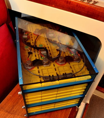
They'll be outside, potentially in direct sunlight, but not if I can help it. They'll be inside a Pelican 0350 case. Whether or not I ventilate the battery compartment of the case is a design issue. That's why I'm thinking about it.
Long term, I think it would be really cool to utilize some PC water cooling tech on each component that sheds heat (Midnite Classic 150, BP-220 LVD, Xantrex 2000W Inverter, and LifePO4 battery). This would be awesome, because I could have the radiator on the outside of the case and have all of the other components inside the water tight case with the lid closed.
However, in the short term, my plan is just to open the case lid and place those components that shed the most heat above the case lid line so they'll have access to air flow. The battery will be below that line inside the guts of the case, but I can add a fan and a vent hole in the top plate of the case so the battery heat has somewhere to go.Leave a comment:
-
Are your batteries outside, in direct sun, enclosed in a box, no or little ventilation, and discharging at 1 to 5C?
or
Setting in your cool basement in the open air doing light duty work?
It is highly unlikely you ever have to worry about over heating. Just guessing due to the fact you have a basement you should be more worried about Winter and freezing temps.
However it is easy to tell if your batteries are getting to warm. If you cannot touch them and hold your hand on them because they are to warm, time to worry and take action. Turn off whatever is turned on.
What I can tell you from experience of running a lot of lithium batteries ran at 50C continuously until discharged in the summer outside, the batteries do not get warm enough I cannot comfortable hold, with one exception, a damaged cell. In your low rate or range up to 2C operating in your conditions the batteries should never feel warm to touch unless you have a cell problem. If you feel a cell getting warm, replace it. Guarantee you the Ri shot up which is what generates the heat. As temps go up, Ri goes down.
FWIW do not compare A123 Cells to your cells. That would be quite an insult to A123 as they are far superior to any of the Chi-Com Prismatic Cells. That is why they cost 3 to 5 times more than you paid per wh.
If you were to compare say 50 of the A123 Cells in parallel which is equivalent to one of your cells what would you expect the Ri to be? We know yours are roughly 2.5 milli-ohms. What would A123 be? Well each A123 18650 cells are 5 milli-Ohms each, twice that of your single cell. If we connect 50 in parallel to equal your capacity the Ri drops from 5 milli-ohms to 100 micro-Ohms. That is 1/25th of what your cells are. That means you would have to use 25 of your cells in parallel to equal A123 Ri. Worth noting A123 does not own the lowest Ri award. They are in the middle of the pack.
So how does that effect you on say 2C discharge. Well your cell voltage sags 5 volts (2 volts on 4S 12 volt battery) and generates 100 watts as waste heat. Let's stop and think about that for a minute. Your pack voltage is 13.6 volts fully charged up connected to your Inverter with your LVD set to 12 volts. We hit the batteries with a 200 amp load, and your battery voltage sags to 11.6 volts. Whats happens to the LVD? Nothing wrong with your battery, it is fully charged. Why did the lights go out? Your LVD operated right?
If you used A123 of same capacity your voltage sag is .02 volts and you loose 4 watts. Your Inverter and my EV are Happy Happy with 13.58 volts.
What I am driving at here here is Ri explains and answers most all your questions. That is why I ran you through the drill.Last edited by Sunking; 08-04-2016, 12:39 PM.Leave a comment:
-
That's pretty interesting. I note two things:
1. It says they used 2.2ah A123 cylindrical cells. Probably prismatic GBS cells won't perform anywhere near as well.
2. That graph shows AH throughput on the X axis, not cycles. It's not clear whether 1000 ah throughput means 500 cycles, or 250 cycles.
This might actually be a better graph:

From that graph, it appears you can expect a max of 1000 cycles from a cylindrical cell at 90% DOD and 60C.
However, when you look at the actual matrix of cells they used for testing:

It appears only two cells where tested at 60C and 90% DOD, and they only made it to 754 and 518 cycles, respectively. So, I'm not really sure what's up with the other graph. I'd personally look at the matrix. It appears to be the most telling. At 45C and 80% DOD and C/2 rate you might be able to expect 2000 cycles from a cylindrical cell. 2C appears fairly untested, but what they did test looks super weird. It appears to perform BETTER than C/2 at 60C and 90% DOD. Weird.
Prismatic will probably fair a little worse in every way.Last edited by createthis; 08-04-2016, 10:37 AM.Leave a comment:


Leave a comment: