-
Simon you are full of crap. You can look the info up and see it for yourself. A varible Power Supply can go to 0% if designed to go mili-volts, But for a solar controller on a battery has no need to go to zero and will always bbe in a state of On to some degree. You can read it right out of Fairchild and TI application notes. Geez you dunno chit about electronics or batteries. Why the hell do you think controllers cannot operate without a battery. If they could you could bypass the battery and operate directly from the controller if it worked the way you you imagined. .Last edited by Sunking; 04-21-2016, 07:44 PM. -
When you say "slowly," what kind of time frame would be typical? I observed the GV-5 first indicating full charge for at most a couple of seconds, and then showing high battery voltage.
I forget, do you speak from experience with the GV-5?
Do you think any of the 5 scenarios in my last post could be valid?Leave a comment:
-
You are nearly right, the GV-5 should never let the voltage get above 14.2 volts, it should have back down the current to match what the battery wanted. When the charge voltage rises to 14.2V and changes to CV the battery hasn't finished charging. The 200mA that you are seeing is the battery still charging. This current will slowly taper off to zero as the battery reaches full charge. It is because your GV-5 is "leaking current" that the voltage went up to 18 volts. Rather like you putting your finger in a leaky tap and feeling the water pressure go higher and higher.
I would call it a design flaw or it could be a defective unit. I think it stems from the fact that the GC-5 was originally designed for Lead Acid batteries which do have high leakage so the current being supplied by the GV-5 to a lead acid battery would never get down to zero.If so, then it seem's you're implying that this is a design flaw. I guess it could also have been a defective unit. But could it be something else? Perhaps it's an issue of timing? Maybe the GV-5 backed the current down too slowly? Could mismatches in some other charging parameters have resulted in the GV-5's failure to keep the voltage down?
Very good questions.I'm waiting for Bioenno's answers to 2 questions: 1) under what conditions will the battery reconnect after it has disconnected due to high charging voltage; and 2) what's the max voltage the BMS can handle.
Simon
Leave a comment:
-
Absolute rubbish, all MPPT controllers do have a load connected to them internally, it is their own control electronics. It doesn't take any extra circuitry to modulate to 0%, it is just software.
Why can't a controller go to 0% modulation?MPPT controllers have large filter capacitors on the output. That capacitor is to hold a charge in between on/off times of the controller. During the off time, the capacitor discharges into the load or battery. If you open the circuit, there is no place for the capacitor to discharge. The fact that no controller can completely shut off or go to 0% modulation it keeps pumping some energy into the capacitor keeping it fully charged up because it has no place to go.
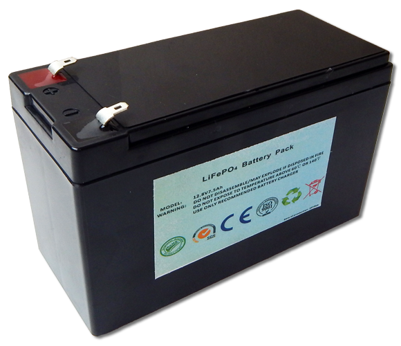
Absolute rubbishThe issue is your battery has a PCM aka Protection Circuit Module as you noted. The two ports, one for charge, and the other for discharge tells you the battery has a HVC circuit to disconnect from the charger when fully charged up. Your battery is simply not compatible with solar charge controllers.
It is Dave C's PCM that protected his battery from damage.The issue again is your battery and its PCM, not the controller. Best solution is to get a standard 12 volt Lithium battery as I linked too earlier. Something like this one. Stay away from batteries with a PCM and two ports. Click this link to see what is available. Take note some are PCM, stay away from them.
I may not have time to answer any further posts for a few days. I will be back
Simon
Leave a comment:
-
Yes, of course. Measuring the voltages is what finally just occurred to me. Unfortunately, I don't have a GV-5 on hand. But I could charge up the battery with the 14.6V AC charger and see what the voltage is when it switches to CV.
I think we've both been looking at this too narrowly. I think this could have happened for any of the following reasons:
1) The controller simply failed to prevent the voltage from rising to the battery's HVD.
2) The controller's actual CV voltage was higher than specified, and must have been at or above 14.6V.
3) The battery's actual HVD is lower than specified, and must be at or below 14.2V.
4) Both controller CV and battery HVD were different than specified and overlapping
5) Some other charging parameter mismatch. I would have no idea what this could be. Is this even possible?
Actually, the thought occurs to me that Genasun might have sent me a custom programmed unit by mistake. That's one possibility that might correspond to number 2 above.
As an aside, again, the manufacturer assured me that the two ports on the battery don't perform different functions, and my experience confirms this. They are both soldered to the same points on the battery pack. They just provide two different connector types, one for the AC charger, and one for a power pole connection for both charging and load. The barrel connector would also supply a load.Leave a comment:
-
It is real dang simple to tell what is going on. Put the battery on th echargger and wait for it to disconnect. Measure the voltage on the Charge Port from the GV5, and the Load Port on the Battery. Bet you $100 you see Voc from the GV5 and 14.2 volts on the battery load port.
There is only one possible way for that to happen. The GV5 output is open circuit. Why? Because your battery HVC disconnected. If the GV5 did charge the battery up to 18 volts (impossible), the battery would explode before it reached 18 volts.
Try this. Connect the GV5 to the battery load port. Don't use the battery charge port, leave it disconnected.Leave a comment:
-
-
But it won't be an open circuit until the battery has reached 14.6V. If the controller keeps it at 14.2V, it will never be an open circuit unless the battery is physically disconnected. Also, Genasun says that the load terminals on the GV-5 are supplied from the battery only.Leave a comment:
-
No he is absolutely correct. But he assumes you have a battery connected or a load connected. Now ask what happens if you open the circuit (disconnect the battery)? His answer will be do not do that because the regulator is not designed to regulate an OPEN CIRCUIT. It has to have a battery connected like any controller. You gotta get your head wrapped around that.
You have already proven that to yourself in you initial statement. You connected the panel first, the GV5 went into HV alarm. You connected the battery and it charged up. While charging the GV5 dis what it is suppose to do. When the battery charged up, the HVC disconnected the GV5 and it went into HV alarm as it is designed to do.Last edited by Sunking; 04-21-2016, 04:45 PM.Leave a comment:
-
Then what did the Genasun rep mean when he said "Yes the Genasun will hold the battery down at 14.2V. All regulators will have this function to prevent over charge of the battery"? To me, that sounds like the controller is designed to prevent the voltage from rising above 14.2V. Are you saying that he was mistaken, or that I'm misinterpreting him? The PCM doesn't come into play until the battery's voltage has risen to the cutoff, right?Leave a comment:
-
No that is not how it works. Understand the difference between an Open Circuit, and a Load. No MPPT Controller can modulate 0%. To do that takes more circuitry and expense. A Controller is designed to have a battery connected at all times (load) and not be disconnected (open circuit).
MPPT controllers have large filter capacitors on the output. That capacitor is to hold a charge in between on/off times of the controller. During the off time, the capacitor discharges into the load or battery. If you open the circuit, there is no place for the capacitor to discharge. The fact that no controller can completely shut off or go to 0% modulation it keeps pumping some energy into the capacitor keeping it fully charged up because it has no place to go.
The issue is your battery has a PCM aka Protection Circuit Module as you noted. The two ports, one for charge, and the other for discharge tells you the battery has a HVC circuit to disconnect from the charger when fully charged up. Your battery is simply not compatible with solar charge controllers.
As for the GV5 it will work, but you have to put up with nuisance High Voltage alarm. The GV5 gets its power from the solar panel where others get their power from the battery. A possible work around is to keep a gizmo connected to the battery load port. So when the battery reaches full charge, the gizmo load shunts enough power to keep the battery connected to the GV5 which will maintain 14.2 volts and FLOAT the battery.
The issue again is your battery and its PCM, not the controller. Best solution is to get a standard 12 volt Lithium battery as I linked too earlier. Something like this one. Stay away from batteries with a PCM and two ports. Click this link to see what is available. Take note some are PCM, stay away from them.
 Last edited by Sunking; 04-21-2016, 04:26 PM.
Leave a comment:
-
Okay, let me see if I understand what you're saying. The GV-5 should never have allowed the battery to reach 14.6V. It should have backed down current to the battery's leakage current (200mA, I thnk) once it reached 14.2V, thus preventing the voltage from drifting upwards any further. But because it's a "leaky tap" it allowed higher current to pass, thus causing the battery voltage to reach the high charging voltage disconnect point. Is that what you're saying?
If so, then it seem's you're implying that this is a design flaw. I guess it could also have been a defective unit. But could it be something else? Perhaps it's an issue of timing? Maybe the GV-5 backed the current down too slowly? Could mismatches in some other charging parameters have resulted in the GV-5's failure to keep the voltage down?
I'm waiting for Bioenno's answers to 2 questions: 1) under what conditions will the battery reconnect after it has disconnected due to high charging voltage; and 2) what's the max voltage the BMS can handle.Leave a comment:
-
Ha Ha Ha, here is the response
Sorry I didn’t respond to this yesterday. Yes the Genasun will hold the battery down at 14.2V. All regulators will have this function to prevent over charge of the battery.
This was my question,
If one connects the GV5 to an LFP battery and starts charging the voltage will rise to 14.2 volts and then the current will drop to virtually zero as the "leakage" current for an LFP is very small. Under these circumstances what will happen to the output of the GV5, will it stay at 14.2 volts or will it drift up towards the solar panel voltage?Diverting the power is only one alternative, the other is to cut back on the the amount of power taken from the panel, rather like turning off a tap. The problem with the GV5 is that it is a leaky tap and can't be turned completely off. If you want to keep the voltage down at 14.2 volts you only have to use the leakage, not the full current.Let me see if I understand this correctly: It seems to me that the only alternative to passing panel OCV to the open battery terminals would be for an MPPT controller to divert all of the power from the panel to a resistive load. (I gathered this from the Wikipedia article on MPPT.) If this is true, wouldn't such a load add considerable weight to a controller? If so, it might explain why other MPPT controllers I've seen are so much heavier than the GV-5. Most are upwards of a pound, where as the GV-5 is only a couple of ounces.
If Bioenno said that 20 volts is not a problem them you are OK. Did they give you a absolute maximum voltage that you mustn't go above?If the above is true, then in my case, the lightness of the GV-5 is a plus that far outweighs the annoyance of seeing an error condition, because I'm assured by Bioenno that their BMS is not affected by the 18-20V that the GV-5 will pass to it.
Simon
Leave a comment:
-
Simon,
Thank you for that info. I look forward to hearing about what Genasun has to say.
Let me see if I understand this correctly: It seems to me that the only alternative to passing panel OCV to the open battery terminals would be for an MPPT controller to divert all of the power from the panel to a resistive load. (I gathered this from the Wikipedia article on MPPT.) If this is true, wouldn't such a load add considerable weight to a controller? If so, it might explain why other MPPT controllers I've seen are so much heavier than the GV-5. Most are upwards of a pound, where as the GV-5 is only a couple of ounces.
If the above is true, then in my case, the lightness of the GV-5 is a plus that far outweighs the annoyance of seeing an error condition, because I'm assured by Bioenno that their BMS is not affected by the 18-20V that the GV-5 will pass to it.
Leave a comment:


Leave a comment: