
This makes sense.
That disconnect would have to be at some low current threshold so the battery never gets to 0A, right?
So for Sunking's suggestion to be a good one, it must be that either: 1) a drop-in replacement battery simulates leakage during charging; or 2) charging current never actually goes to zero with LFP--very close to it, but high enough to let the controller know that a battery is still there. Unless you two agree on this (or someone else weighs in), the only way for me to know would be to test with a battery that has no low current disconnect. Do you agree that as a rule, drop-in batteries have no above-zero low current threshold? Would this be a worthwhile test?
-
That is the correct understanding. If you look at the situation from the battery's point of view the controller is a bit like a switch between the solar panel and the battery. If the switch is on, or partially on current will flow into the battery. It is up to the controller to regulate this flow to keep the correct battery voltage. When the battery is full there should be no current flow to the battery. As far as the battery sees, the switch in the controller will be turned off, i.e. an open circuit.
Not quite true. If the battery is drawing zero current the battery voltage will go up to Voc unless the controller disconnects the panel from the batteryNow I understand that a controller could only go to Voc in the absence of a battery; it doesn't do so because of its own decision to send 0A to the battery.
The controller should never allow Voc at the battery terminals.But I still don't understand WHY any controller would allow Voc at the battery and load. I would expect to find Voc at the panel terminals, but not at the battery or load terminals.
SimonLeave a comment:
-
I would be concerned if the voltage ratings of the components in the Elecraft radio are only 15 volts and if this were the case would be concerned operating it at 14.2V. If a manufacturer states an operating voltage of 15 volts they should have some sort of safety margin, just as someone building a house wouldn't want it teetering on the the edge of collapsing. I would think 5 volts is not an unreasonable bare minimum safety margin for this application. Running components, especially electrolytic capacitors right at the top of their operating voltage range will usually decrease their life span and is to be avoided. Would be an interesting exercise to take one of the radios apart and check all the components in the power input circuit or to talk to one of the design engineers who designed it.
SimonLeave a comment:
-
I agree, this would only work if you only have the resistor connected when the GV5 is charging. If it was your intention to have the GV5 or for that matter any MPPT controller connected to the battery all the time you will have to check whether or not the controller would draw power from the battery when there was no power coming in from the solar panel.
This is the problem. Because of the virtually zero leakage current of LFP batteries the current going into a LFP battery will go down to virtually zero if you charge it to a fixed voltage. Now, if as Sunking maintains, no MPPT controller is capable of providing a regulated output unless there is some load on it when the current gets to whatever the minimum that the controller will loose regulation at the voltage will start creeping up as the battery gets to a higher and higher SOC. If this voltage gets too high you will start damaging the battery.Is there any LFP battery that would allow a controller to remain at some small current above zero at CV? From what I've learned here, I would say no. If my thinking is correct, then I question Sunking's reasoning that it would be possible to find a battery that would keep this controller from going to panel voltage. Of course, I'm willing to learn if I'm wrong.
Now, I don't think this is correct. I think that if not all then the majority of MPPT controllers will be able to regulate the voltage without any load so you will be able to charge LFP batteries with an MPPT controller but the issue of whether an MPPT controller is capable of working without a load is something to bear in mind.
The problem with your Bioenno battery is that it will suddenly disconnect the battery from the MPPT controller while there is still current flowing. IMO a well designed MPPT controller would be able to cope with this and only produce a small transient voltage rise that would not be enough to damage equipment connected to it.
SimonLeave a comment:
-
Thanks for all of this information. I will need to go through it a few times to get my head around it.
Here's what I think has misled me to believe that all batteries, including drop-in SLA replacments, would cause Voc in this contoller: I know from this thread that in order to keep a battery at CV, the controller has to eventually stop sending current to it, i.e., it has to lower current to 0A. In my limited understanding, I equated "lowers current to 0A" with "goes to open circuit". Now I understand that a controller could only go to Voc in the absence of a battery; it doesn't do so because of its own decision to send 0A to the battery.
I'm more curious now to test a drop-in battery. But I'll probably stick to my chosen solution, because it virtually eliminates the possibility of over voltage at the radio due to equipment or human error.
You've succeeded in helping me to understand the conditions under which a controller CAN go to Voc. But I still don't understand WHY any controller would allow Voc at the battery and load. I would expect to find Voc at the panel terminals, but not at the battery or load terminals.
Last edited by Dave C; 04-29-2016, 12:35 AM.Leave a comment:
-
Then you do not understand what they are telling you, and you might not have framed your question correctly.
If would be Impossible for the GV5 to go to Voc with a battery connected. I have told you this many times. To take that battery from 14.2 volts to 18 volts would require about 50 amps of charge current. It can only go to 18 volts if the resistance is open circuit. I pointed you to a tutorial that explains that. If you had read it you would understand.
But here is the run down. Those battery cells based on their size have an Internal Resistance of roughly .02 Ohm or 20 milli-Ohms each. With 4 in series will add up to .080 Ohms. To take that battery from 14.2 volts to 18 volts would require a charge current of [18 volts - 14.2 volts] / .08 Ohms = 47.5 Amps. To push that much current would require a minimum 900 watts and a controller capable of 50 amps.
If you look at IR curves on Solar Panels will also tell you it is impossible. A solar panel is a Current Source. Maximum current is generated at 0 volts called Isc (curent short circuit) At Vmp current is roughly 80% of Isc. From Vmp up to Voc current goes down to ZERO amps sharply. So even if you had a 900 watt panel with a Vmp at 16 volts, current would drop to zero amps at Voc. You lack of understanding is forcing you to make poor decisions.

Your 28 watt panel on its best day can only generate 2 amps of charge current. That means the highest voltage possible from the GV5 into your battery (assuming it is connected) is = 14.2 volts x [2 amps x .08 Ohms] = 14.216 volts.Last edited by Sunking; 04-28-2016, 11:03 PM.Leave a comment:
-
"You have been given all your options. Pick one." What is this, "Kung Fu"?
The way I understand it from Genasun, when charging goes to 0A, the GV-5 goes to panel voltage for a couple of seconds before it settles into CV. If the GV-5 has to go to 0A to keep a drop-in-replacement battery at CV voltage, then even though the battery doesn't disconnect like the Bioenno battery does, it wouldn't eliminate the problem. I'll get a drop-in battery and experiment at some point.
Here's what Elecraft says about over voltage:
I've decided that I don't want to try floating any battery with this controller. Even with a completely compatible battery, an accident as simple as kicking a battery lead loose would fry my radio. In fact, although it's probably overkill, I might not float any battery with any controller with this radio in the loop.The absolute maximum input voltage is 15.0VDC. Any higher than that, or any voltage transients, will likely damage the PMOS switching power transistor that turns on the rig, and the PA transistors. Such damage would not be covered by the warranty.
So you need to do whatever is necessary to prevent more than 15.0VDC from ever being presented to the rig, either when it is OFF or ON. We have seen KX3s damaged if this happens.
It could be done by adding an external voltage regulator between the rig and the battery/solar panel charger, or some type of transient voltage suppressor, or by using a different solar controller that never allows more than 15.0VDC across the battery.
When I get the controller, I'll experiment with a resistor at the load terminals. I wouldn't connect one permanently, though, because, as you said, it would use up the battery a lot faster.Leave a comment:
-
The battery just needs to stay connected PERIOD. That is what you do not understand. A solar panel and charge controllers are current sources. It requires the battery to turn it into a VOLTAGE SOURCE so the Controller can regulate the voltage. You have been given all your options. Pick one.
1. If it were me I would just connect the radio to the GGV5 Load Port, or Battery Discharge Port, turn it on, leave it on, walk away and call it good. It will work just fine.
2. Get a battery that is compatible and does not disconnect itself from the controller.
Take your pick. It is not that difficult. The resistor idea may or may not work but comes with a catch. It uses precious power you cannot afford. A 12 volt 4.5 AH battery only has 54 watt hours with only 44 usable. If that resistor burns 1 watt, you are using 50% of the capacity of the battery in a day making useless heat. That is on top of what the radio uses. A recipe for a dead battery.
Leave a comment:
-
-
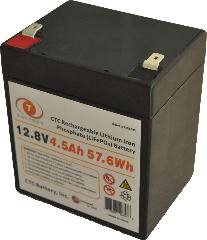
OK then you have not learned a thing or listened over the week. Any drop in replacement LFP battery will do it. Again the issue is your battery disconnecting when charged. A drop in replacement does not do that. They work just like any Pb battery. This one here is 12 volt 4.5 AH lithium battery made for alarm panels that use a Float Charger. You can even buy them for a car battery. It wil float at 13 to 14.6 volts and does not take any special charge or solar ccharge controller. Note it looks like any AGM battery with just one set of terminals. No separate charge and discharge port. There are hundreds of them for sale, all you gotta do is look.
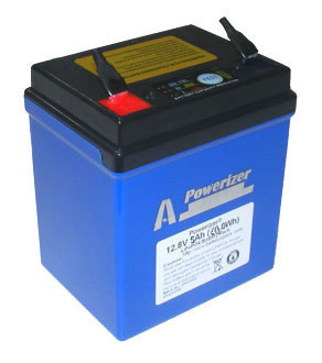
Here is another one in your size.
Here is a hint: Look for 12 volt Lithium Alarm panel and motor cycle batteries.
Last edited by Sunking; 04-28-2016, 06:01 PM.Leave a comment:
-
-
I will be interested to see what happens when I test with a resistor. But I don't think a 1W resistor, connected at all times, is a good solution, as it will drain the battery.
At this point, floating the battery is not guaranteed safe with this controller. So, I'm setting up a project box that will contain a Watt's Up power meter and two DPDT ON-OFF-ON switches, one to connect either the panel or the load to the controller or disconnect both, and the other to reverse polarity at the power meter (to allow it to monitor either charging or discharging current) or disconnect it. I've wanted to house my fuses and other wire connections in a sealed box of some kind anyway, and I think this box will add less than a pound.
Your power logger sounds like a nice project. Wish I had time to get up to speed and experiment. Let me know if you come up with something like this.
Is there any LFP battery that would allow a controller to remain at some small current above zero at CV? From what I've learned here, I would say no. If my thinking is correct, then I question Sunking's reasoning that it would be possible to find a battery that would keep this controller from going to panel voltage. Of course, I'm willing to learn if I'm wrong.Leave a comment:
-
I thought you might get a reply like that from the radio manufacturer.
Maybe an easier solution might be to try putting a load resistor on the GV5 output so it always has a load on it regardless whether the battery is connected or not. May I suggest you try an experiment by placing a 330 Ohm 1 Watt resistor across the output of the GV5 and see if it an keep the output voltage regulated at 14.2V.
A specification for your battery meter might be:
Bidirectional current and voltage logger that hooks up to smartphone or computer via bluetooth.
Logger has to be low power consumption and preferably go to very low power standby mode when battery is not being used.
Smartphone and computer software to display battery SOC and voltage.
Don't think anything like this exists, just an idea.
Simon
Leave a comment:
-
The KX3 can't handle more than 15V, including transients, even when powered off. So I'm going to have to be able to switch between either panel connected or load connected, never both at the same time. I think I need some kind of double-throw ON-OFF-ON switch that has no common connection, so I can choose between two independent circuits or turn them both off, It seems like it should be pretty straightforward to find this, but I haven't found one yet. It needs to be IP65 rated.
Sorry for the lame electronics 101 question. I think I would use a DPDT switch, permanently connect the common connectors, and connect the panel and the load to the controller through the appropriate connectors on the switch.Leave a comment:

Leave a comment: