
 Tweet
Tweet
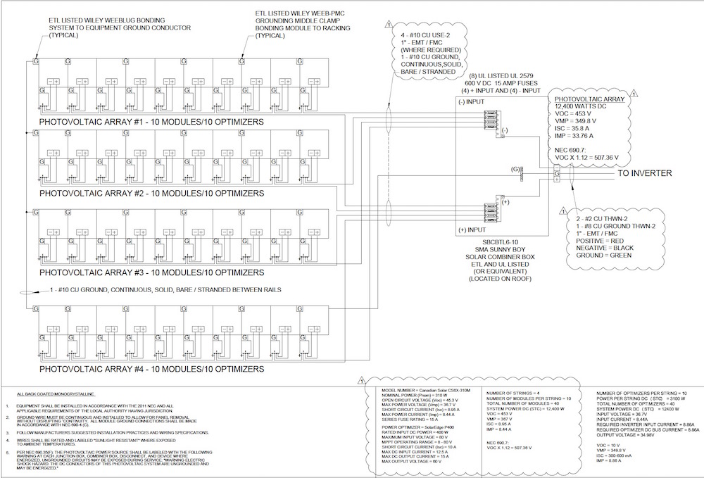
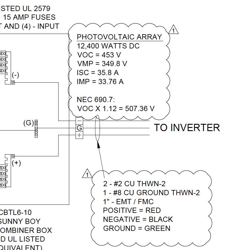
There will be a temperature correction for anything more than 30 deg, which is too low of a temp for an attic in AZ. The design temps used in the permit originally are probably still good choices, but if I recall correctly, even with those corrections 2 AWG is overkill. If HX_Guy can post the design temps from his permit, it will save digging through the threads and getting a magnifying glass out to figure it out.
Edit: And yes, although I think I would be capable of installing my own system, I think the money spent hiring an good installer is worth it.
Edit: And yes, although I think I would be capable of installing my own system, I think the money spent hiring an good installer is worth it.


Comment